Device for utilizing waste heat

a waste heat and device technology, applied in steam engine plants, mechanical equipment, machines/engines, etc., can solve the problem of the lowest available temperature level in the coupling heat exchanger (condenser), and achieve the effect of shortening the warm-up phase reducing the cooling of the internal combustion engine, and saving weight and installation spa

Active Publication Date: 2012-08-09
ROBERT BOSCH GMBH
View PDF11 Cites 21 Cited by
  • Summary
  • Abstract
  • Description
  • Claims
  • Application Information

AI Technical Summary

Benefits of technology

[0005]At the operating temperature of the internal combustion engine, this approach results in the lowest available temperature level in the coupling heat exchanger (condenser) of the steam circuit. The utilization of the waste heat of the internal combustion engine may be used for shortening the warm-up phase of the internal combustion engine. Furthermore, the possibility exists for utilizing the waste heat of the internal combustion engine for heating the interior of the vehicle, which takes place in particular at a low engine load. Furthermore, it is possible to reduce the cooling of the internal combustion engine. The temperature regulation of the internal combustion engine is also not falsified when a conventional expansion material thermostat is used. Furthermore, the approach according to the present invention is characterized in that no additional radiator is needed for a low-temperature cooling circuit. It would be possible to implement this using a separate cooling circuit for the coupling heat exchanger (condenser), which may, however, be dispensed with, resulting in a saving of weight and installation space. Furthermore, negative effects on the drag coefficient, which could otherwise occur, are avoided.
[0006]According to the approach according to the present invention, the waste heat of the steam circuit is coupled into a first circuit of the engine cooling system via a coupling heat exchanger during the warm-up phase of the internal combustion engine for warm-up acceleration, in order to minimize the fuel consumption of the internal combustion engine. The coupling heat exchanger is in particular a condenser through which a cooling fluid of the internal combustion engine flows. After the warm-up phase of the interna

Problems solved by technology

At the operating temperature of the internal combustion engine, this approach results in the low

Method used


Image

  • Device for utilizing waste heat
  • Device for utilizing waste heat
  • Device for utilizing waste heat

Examples


Embodiment Construction

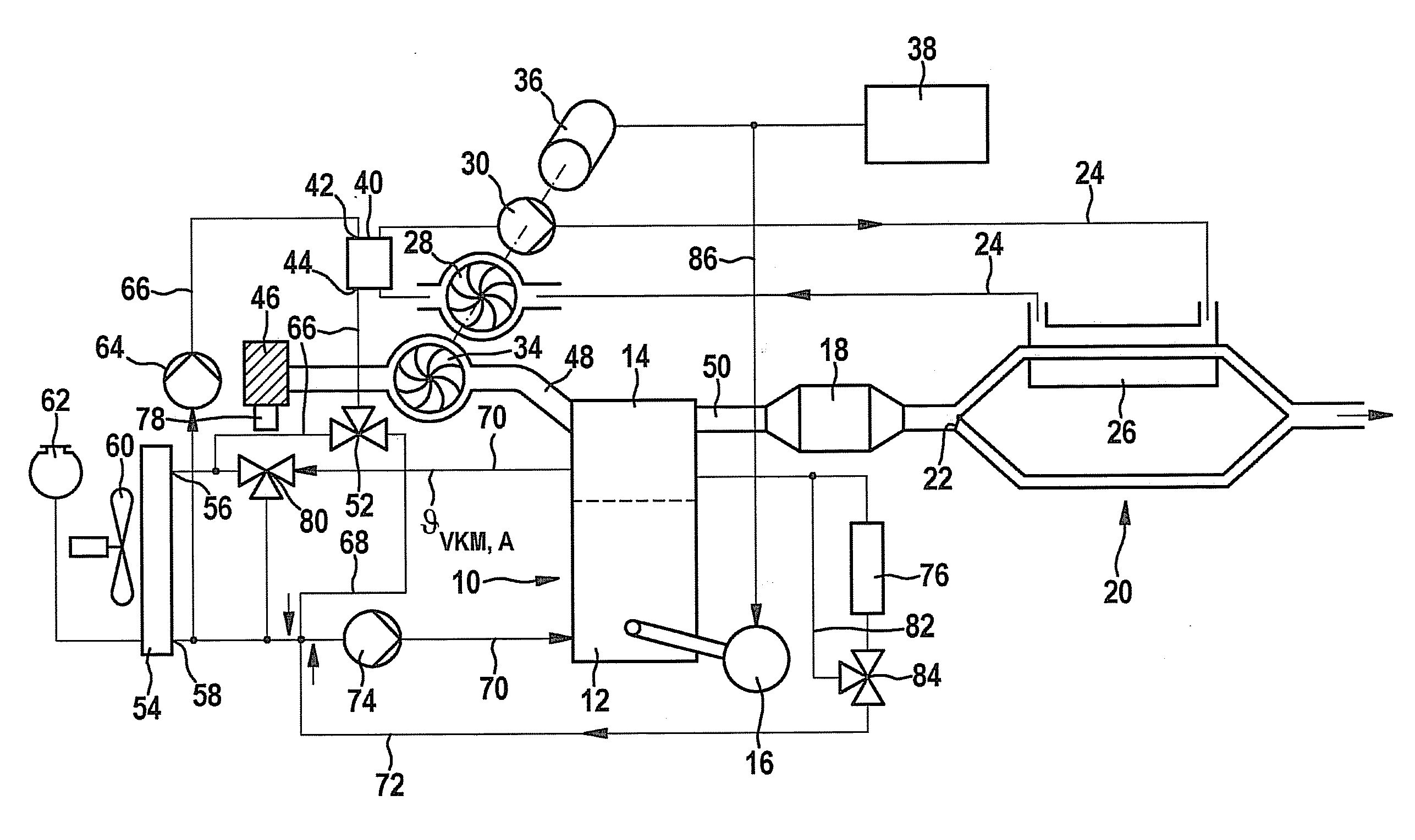
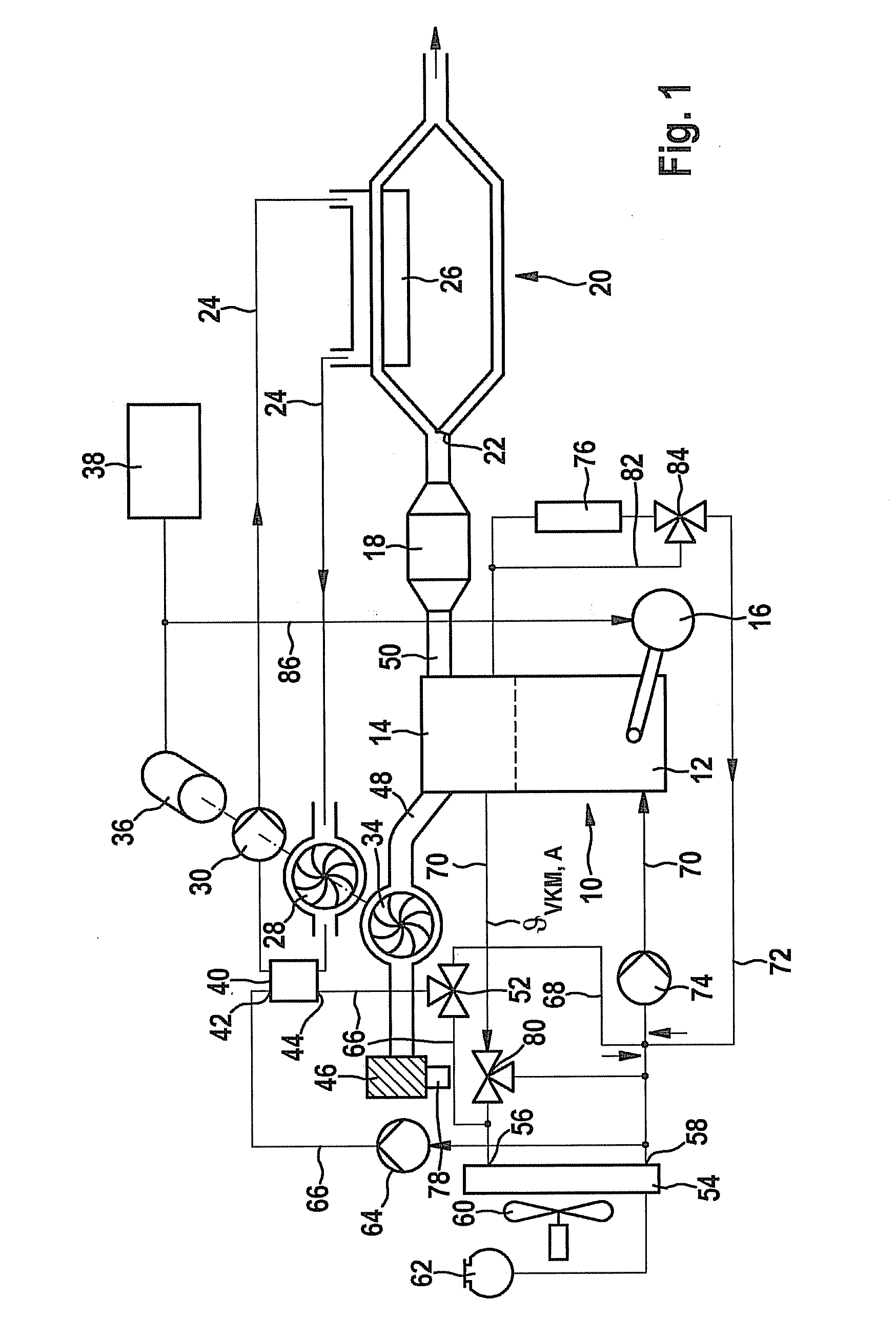
[0009]The representation in the figure shows in greater detail that an internal combustion engine 10 includes an engine block 12. A cylinder head 14 is located on engine block 12; a starter / generator 16 is flange-mounted on the engine block in the area of the crank shaft which is not shown in the drawing. Within an exhaust system 20, internal combustion engine 10 includes an exhaust gas catalytic converter 18, a heat exchanger 26 being formed in one branch in exhaust system 20. Heat exchanger 26 is part of a circuit 24 for a working medium, the circuit being in particular a steam circuit according to the approach according to the present invention. Apart from heat exchanger 26, circuit 24 includes a device for utilizing waste heat, which includes an expansion machine 28 and a pump 30. Furthermore, the working medium flows through a coupling heat exchanger 40, i.e., a condenser, within circuit 24, i.e., the steam in steam circuit 24. The working medium of circuit 24, i.e., the steam,...


PUM


Abstract

A device for utilizing waste heat of an internal combustion engine. A heat exchanger of a circuit of a working medium is provided in its exhaust system. A pump is connected upstream from the heat exchanger, the circuit containing an expansion machine. A coupling heat exchanger is located in the circuit of the working medium, the working medium of the circuit and the cooling medium of the internal combustion engine flowing through the coupling heat exchanger.

Description

BACKGROUND INFORMATION[0001]German Patent No. DE 10 2006 057 247 relates to a supercharging device in which thermal energy is withdrawn from the exhaust gas of an internal combustion engine via a steam circuit and converted partially into mechanical and electrical energy by a turbine. Unutilized waste heat is discharged to the environment by a separate condenser. A supercharging device is used in particular for supercharging an internal combustion engine. At least one exhaust gas heat exchanger of a circuit of a working medium is situated in the exhaust system. A delivery unit is connected in the circuit of the working medium upstream from the at least one exhaust gas heat exchanger. The circuit of the working medium contains at least one turbine part, via which at least one compressor part situated in the intake system of the internal combustion engine is driven.[0002]A publication “BMW four-cylinder utilizes waste heat for increased performance-engine with turbine” is known from t...

Claims


Application Information

Patent Timeline
IPC IPC(8): F01N5/02F02B37/00
CPCF01K9/003F01K23/065F01N5/02F01P2005/105Y02T10/166F02B33/34F02B39/08F02G5/02Y02T10/16F01P2060/08Y02T10/12
Inventor STEGMAIER, JUERGENCICHON, MARTINSCHMITT, MANFREDSCHMIDT, ACHIM
Owner ROBERT BOSCH GMBH
Why Eureka
Try Eureka