
Fastening Assembly for a Sensor Assembly and Sensor Assembly

Active Publication Date: 2012-11-22
ROBERT BOSCH GMBH
View PDF3 Cites 19 Cited by
  • Summary
  • Abstract
  • Description
  • Claims
  • Application Information

AI Technical Summary

Benefits of technology

[0006]As a result of the proposed inventive design, resonances can be shifted into uncritical frequency ranges above approximately 4 to 5 kHz, and influences of the carrier plate resonances and of other components which are connected to the carrier plate can be reduced by virtue of the fact that the sensor module is positioned on a region of the carrier plate which is not susceptible to interference. As a result, embodiments of the present invention permit housing designs which are optimized in terms of vibration to be made available. This means that the natural frequencies of a housing which encloses the sensor assembly can advantageously be shifted into a frequency range which is above approximately 4 to 5 kHz. Since the eigenmodes of the housing constitute the main cause of interference in the sensor signal, it becomes clear how advantageous it is to decouple the eigenmodes of the housing. Embodiments of the invention not only permit natural resonances of the housing to be decoupled but also the overshoots on the carrier plate to be significantly reduced. Therefore, in particular the installation location of the at least one sensor module on the carrier plate can be decoupled from the eigenmodes of the housing. In addition, the dimensions of the housing can be reduced by virtue of the single-point fixing means.
[0018]The two parts can be joined, for example, by welding or pressing. A circular shape or a rectangular shape can be selected for the geometry of the disk, which entails additional savings in terms of material and weight.

Problems solved by technology

A problem which frequently occurs when inertial sensors in motor vehicles are used is that of interference accelerations which can occur depending on the installation location of the sensor.

Method used


Image

  • Fastening Assembly for a Sensor Assembly and Sensor Assembly
  • Fastening Assembly for a Sensor Assembly and Sensor Assembly
  • Fastening Assembly for a Sensor Assembly and Sensor Assembly

Examples


Embodiment Construction

[0039]In the accompanying FIGS. 1 to 18, identical reference symbols denote throughout elements and / or components which carry out identical or analogous functions.

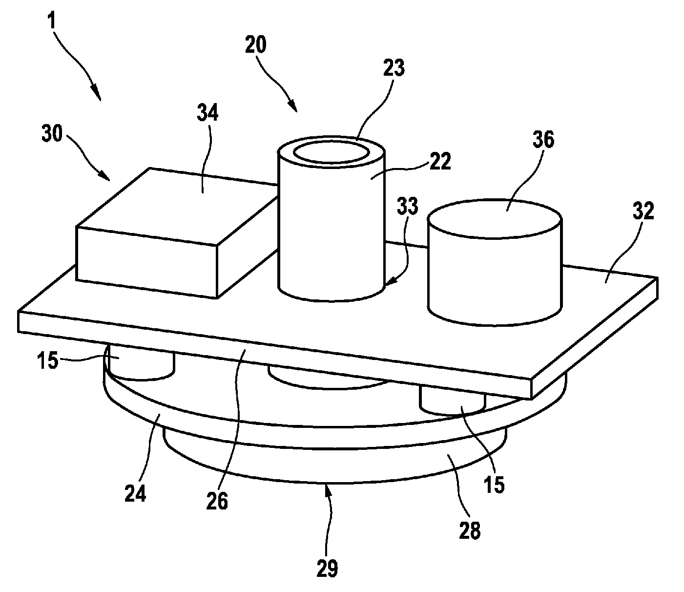
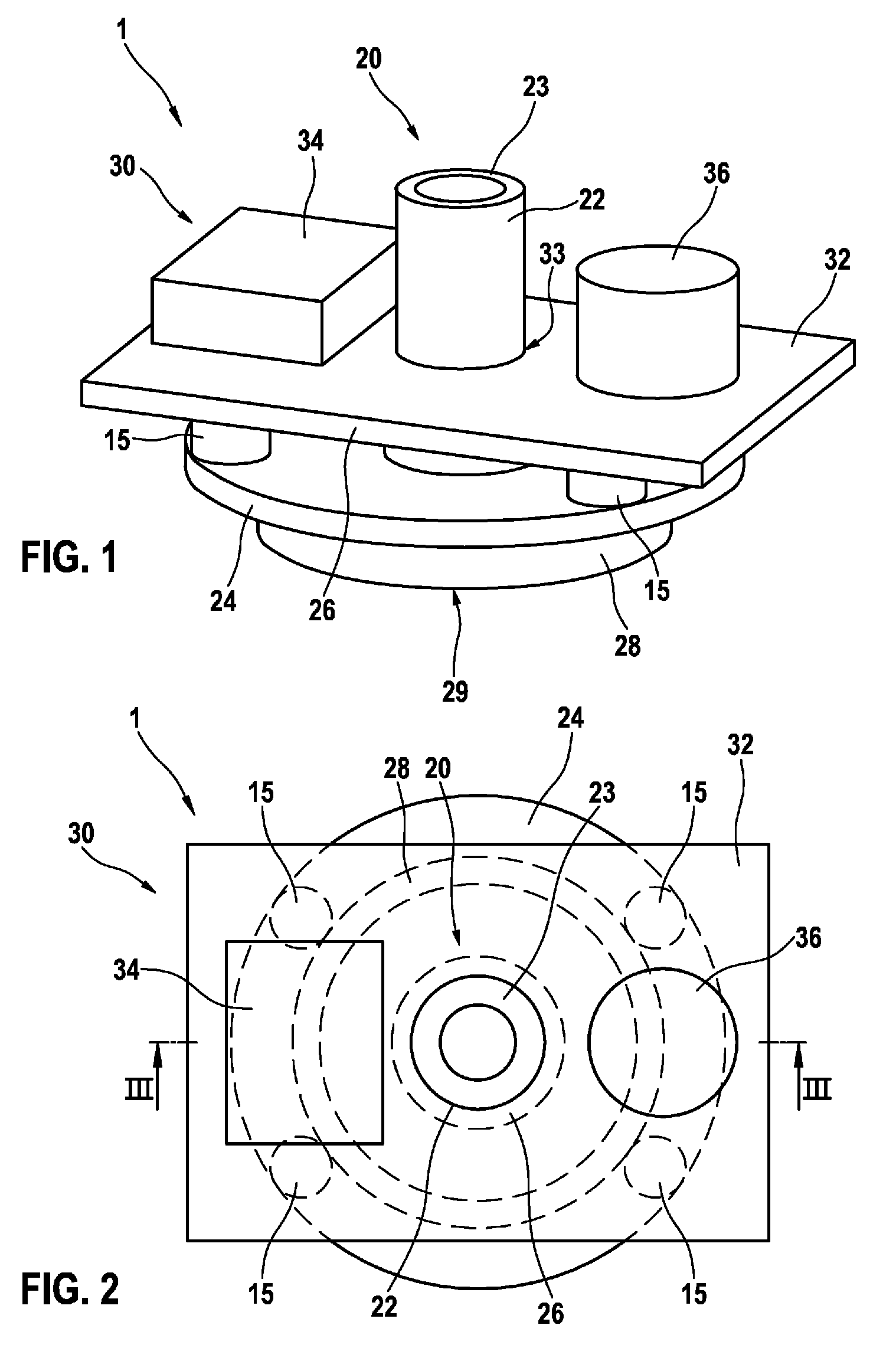
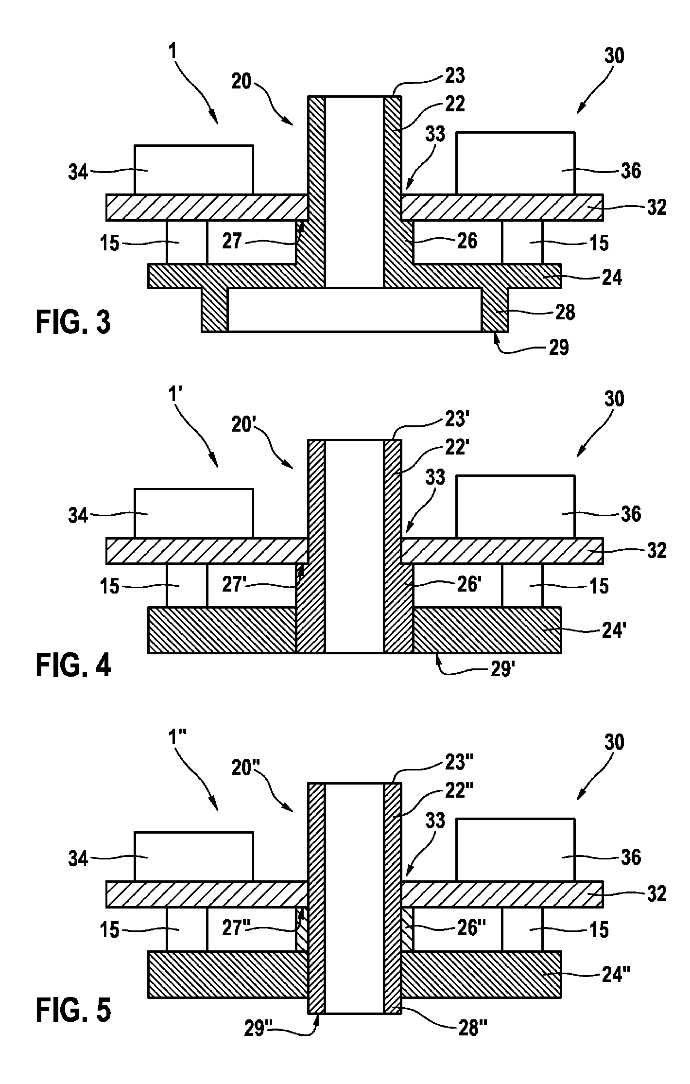
[0040]As is apparent from FIGS. 1 to 3, a first exemplary embodiment of a sensor assembly 1 according to the invention without a housing comprises a metal bush 20 and an electronic assembly 30 with a carrier plate 32, on which a sensor module 34 and a further component 36, embodied for example as a capacitor, is arranged. The sensor module 34 is embodied, for example, as what is referred to as an inertial sensor which comprises micro-mechanical or micro-electromechanical sensors and can be used to measure accelerations and / or yaw rates and / or rotation rates of the motor vehicle with respect to various spatial axes. In addition, the corresponding electronic evaluation circuits can be integrated in the sensor module 34 or arranged on the carrier plate 32. According to the invention, the metal bush 20, which is part of a fast...


PUM


Abstract

A fastening assembly for a sensor assembly has a metal bush and a fastener. It is possible for the metal bush to be connected via the fastener to a vehicle body. The sensor assembly includes at least one sensor module and an associated sensor assembly. The metal bush has a sleeve as a single-point fixing and a plate as a carrier unit for a carrier plate on which the at least one sensor module is arranged. The sleeve is led through a central through-passage in the carrier plate.

Description

PRIOR ART[0001]The invention is based on a fastening assembly for a sensor assembly of the generic type of independent patent claim 1, and on a corresponding sensor assembly of the generic type of independent patent claim 10.[0002]Active and passive safety systems such as, for example, restraint systems such as, for example, airbags, seat belt pretensioners etc. as well as systems for controlling the vehicle movement dynamics such as, for example, ESP, ABS etc. are used in modern motor vehicles. An essential component of such systems are inertial sensors which are used to measure accelerations and / or yaw rates and / or rotation rates of the motor vehicle and are preferably embodied as micro-mechanical or micro-electromechanical sensors. During operation, such sensors are made to move in an oscillating fashion by suitable mechanical excitation, and forces and / or accelerations which occur are measured and evaluated.[0003]German laid-open patent application DE 10 2007 058 965 A1 describe...

Claims


Application Information

Patent Timeline
IPC IPC(8): F16M13/02
CPCG01D11/30G01D11/245
Inventor MIEKLEY, KLAUSWILLIG, RAINERROGGE, BERTHOLDOECHSNER, HERBERTKONSTANTIN, GEORG
Owner ROBERT BOSCH GMBH
Learn More