
Micro-spacing display lamp panel avoiding light crosstalk interference and manufacturing method of micro-spacing display lamp panel

A micro-spacing and optical interference technology, applied in the direction of instruments, electrical components, electrical solid devices, etc., can solve problems such as difficult to achieve production inspection, inability to effectively improve mutual interference of light, inability to precisely control thickness and uniformity of light output effect, etc. Achieving good light-emitting effect, improving display effect and excellent light-emitting efficiency

Pending Publication Date: 2020-02-07
AET DISPLAY LTD
View PDF1 Cites 4 Cited by
  • Summary
  • Abstract
  • Description
  • Claims
  • Application Information

AI Technical Summary

Problems solved by technology

[0003] However, dark grid shielding is similar to the colloid coating method. For LED displays with fine pitch size, the grid or colloid method can no longer accurately control the thickness and uniformity of the light output effect, and cannot effectively improve the mutual interference of light. It is difficult to achieve Meet the standards of production inspection

Method used


Image

  • Micro-spacing display lamp panel avoiding light crosstalk interference and manufacturing method of micro-spacing display lamp panel
  • Micro-spacing display lamp panel avoiding light crosstalk interference and manufacturing method of micro-spacing display lamp panel
  • Micro-spacing display lamp panel avoiding light crosstalk interference and manufacturing method of micro-spacing display lamp panel

Examples


Embodiment Construction

[0039] In order to make the object, technical solution and advantages of the present invention clearer, the present invention will be further described in detail below in conjunction with the accompanying drawings.

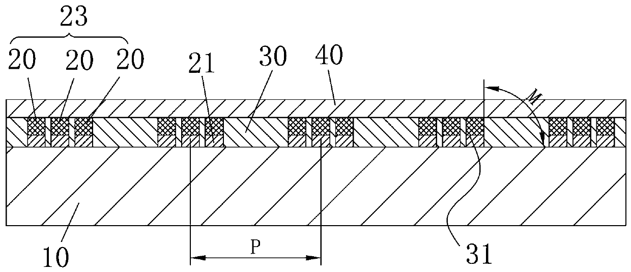
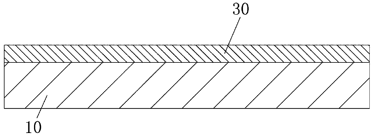
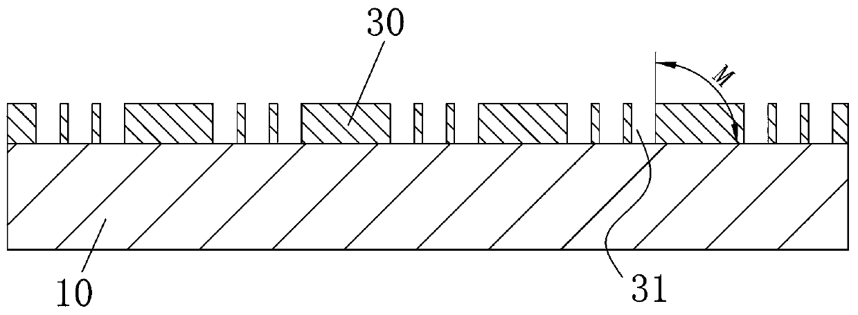
[0040] Such as figure 1 As shown, the first embodiment provided by the present invention, a fine-pitch display light board for avoiding cross-light interference, includes a circuit board 10 , LED chips 20 , a light-shielding layer 30 and a protective layer 40 . The light-shielding layer 30 is attached to the surface of the circuit board 10, and the light-shielding layer 30 is provided with a plurality of accommodation holes 31, and each LED chip 20 is arranged in one accommodation hole 31 and is conductively bonded to the circuit board 10 through the conductive bonding layer 21 to accommodate The inner wall of the hole 31 shields the light emitted from the side of the LED chip 20 ; the protective layer 40 is attached to the surface of the light shielding layer 30...


PUM

PropertyMeasurementUnit
thicknessaaaaaaaaaa

Abstract

The invention provides a micro-spacing display lamp panel avoiding light crosstalk interference and a manufacturing method of the micro-spacing display lamp panel. The micro-spacing display lamp panelavoiding light crosstalk interference comprises a circuit board, LED chips, a light-shading layer and a protection layer, wherein the light-shading layer attaches to the surface of the circuit board,the light-shading layer is provided with a plurality of accommodating holes, each LED chip is arranged in one accommodating hole and is in electric conduction bonding with the circuit board through aconductive bonding layer, and the inner walls of the accommodating holes shelter light rays emitted by the side faces of the LED chips; and the protection layer attaches to the surface of the light-shading layer, and covers the top faces of the LED chips. According to the technical scheme, the light-shading layer can adopt a material having small probability of light transmitting and realizing light absorption, then the shielding and sheltering effects are formed, thus the light interference phenomenon caused by short distances among the LED chips or light-emitting assemblies can be effectively avoided, the influences due to mixing of the light emitted from the side directions of the adjacent LED chips or the light-emitting assemblies are reduced, and therefore, the light outgoing effectis uniform.

Description

technical field [0001] The invention relates to the technical field of LED displays, in particular to a fine-pitch display lamp panel and a manufacturing method thereof for avoiding cross-light interference. Background technique [0002] Chinese Taiwan patent TW201638911A discloses a display, which is suitable for being installed on a vehicle to provide a display image to a user riding on the vehicle. Among them, the light-emitting component is covered with a dark grid shield (the patent attaches Figure 5 A), the dark grid shield is used to avoid mutual interference of the light emitted by the light-emitting components in the opening, and to prevent the pads on the surface of the carrier board from getting wet. [0003] However, dark grid shielding is similar to the colloid coating method. For LED displays with fine pitch size, the grid or colloid method can no longer accurately control the thickness and uniformity of the light output effect, and cannot effectively improve ...

Claims


Application Information

Patent Timeline
Patent Type & Authority Applications(China)
IPC IPC(8): G09F9/33H01L27/15
CPCG09F9/33H01L27/156
Inventor 詹智翔赵春雷
Owner AET DISPLAY LTD
Learn More