Method and device in user equipment and base station used for wireless communication

A technology for wireless communication and user equipment, which is applied in the directions of wireless communication, transmission path separation device, pilot signal allocation, etc., to achieve the effect of reducing complexity

Active Publication Date: 2020-02-07
SHANGHAI LANGBO COMM TECH CO LTD
View PDF2 Cites 7 Cited by
  • Summary
  • Abstract
  • Description
  • Claims
  • Application Information

AI Technical Summary

Problems solved by technology

Some typical application scenarios, such as URLLC (Ultra-Reliable and Low Latency Communications, Ultra-Reliable and Low Latency Communications), put forward high requirements for delay, and also pose new challenges for inter-cell handover

Method used


Image

  • Method and device in user equipment and base station used for wireless communication
  • Method and device in user equipment and base station used for wireless communication
  • Method and device in user equipment and base station used for wireless communication

Examples


Embodiment 1

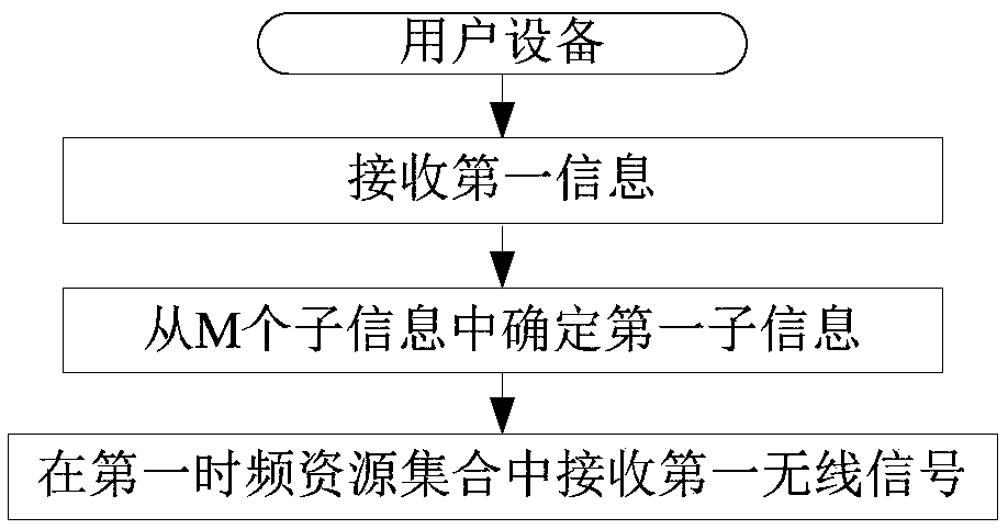
[0145] Embodiment 1 illustrates the flowchart of the first information, the first sub-information and the first wireless signal; as attached figure 1 shown.

[0146] In Embodiment 1, the user equipment in this application receives first information; determines the first sub-information from M pieces of sub-information; and receives a first wireless signal in a first set of time-frequency resources. Wherein, the first information includes the M pieces of sub-information, each of the M pieces of sub-information indicates a reference signal group, and a reference signal group includes at least one reference signal; the first sub-information indicates the first reference signal Signal group; the reference signal in the reference signal group indicated by at least one of the M sub-information is sent by the first serving cell, and the first serving cell is not added by the user equipment; the user equipment assumes that the The transmitting antenna port of the first wireless signa...

Embodiment 2

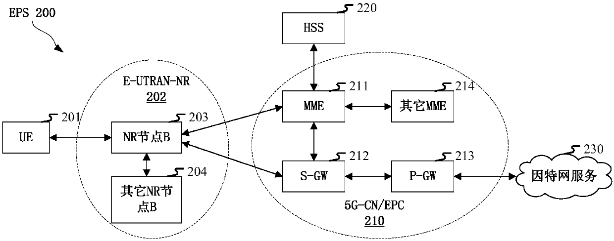
[0217] Embodiment 2 illustrates the schematic diagram of network architecture, as attached figure 2 shown.

[0218] attached figure 2 The network architecture 200 of LTE (Long-Term Evolution, long-term evolution), LTE-A (Long-Term Evolution Advanced, enhanced long-term evolution) and a future 5G system is described. The network architecture 200 of the LTE, LTE-A or 5G system may be referred to as an EPS (Evolved Packet System, evolved packet system) 200 . EPS 200 may include one or more UE (User Equipment, User Equipment) 201, E-UTRAN-NR (Evolved UMTS Terrestrial Radio Access Network-New Radio) 202, 5G-CN (5G-CoreNetwork, 5G core network) / EPC (Evolved Packet Core, Evolved Packet Core) 210 , HSS (Home Subscriber Server, Home Subscriber Server) 220 and Internet service 230 . Among them, UMTS corresponds to Universal Mobile Telecommunications System (Universal Mobile Telecommunications System). EPS 200 may be interconnected with other access networks, but these entities / in...

Embodiment 3

[0226] Embodiment 3 illustrates a schematic diagram of an embodiment of the wireless protocol architecture of the user plane and the control plane, as shown in the attached image 3 shown.

[0227] attached image 3 is a schematic diagram illustrating an embodiment of a radio protocol architecture for a user plane and a control plane, with image 3 The radio protocol architecture for UE and gNB is shown with three layers: Layer 1, Layer 2 and Layer 3. Layer 1 (L1 layer) is the lowest layer and implements various PHY (Physical Layer) signal processing functions. The L1 layer will be referred to herein as PHY 301 . Layer 2 (L2 Layer) 305 is above PHY 301 and is responsible for the link between UE and gNB through PHY 301 . In the user plane, the L2 layer 305 includes MAC (Medium Access Control, Media Access Control) sublayer 302, RLC (Radio Link Control, Radio Link Layer Control Protocol) sublayer 303 and PDCP (Packet Data Convergence Protocol, packet data convergence protoc...


PUM


Abstract

The invention discloses a method and a device in user equipment and a base station used for wireless communication. The user equipment receives the first information and determines first sub-information from the M pieces of sub-information; a first wireless signal is received in a first set of time-frequency resources, wherein the first information comprises M pieces of sub-information, each pieceof sub-information in the M pieces of sub-information indicates a reference signal group, and each reference signal group comprises at least one reference signal. The first sub-information indicatesa first reference signal group, wherein a reference signal in a reference signal group indicated by at least one piece of sub-information in the M pieces of sub-information is sent by a first servingcell, and the first serving cell is not added by the user equipment; and the user equipment assumes that the sending antenna port of the first wireless signal is quasi-co-located with the sending antenna port of any reference signal in the first reference signal group. According to the method, the performance improvement caused by serving cell switching is obtained, and time delay and service interruption are avoided.

Description

technical field [0001] The present application relates to a method and a device in a wireless communication system, in particular to a method and a device in a wireless communication system supporting multiple antennas. Background technique [0002] In the LTE system, inter-cell handover (Handover) is controlled by the base station based on UE (User Equipment, user equipment) measurement. The inter-cell handover in 3GPP (3rd Generation Partner Project, third generation partnership project) R (Release, version) 15 basically follows the mechanism in LTE. In the NR (New Radio, new radio) system, more application scenarios need to be supported. Some typical application scenarios, such as URLLC (Ultra-Reliable and Low Latency Communications, Ultra-Reliable and Low Latency Communications), put forward high requirements on delay, and also pose new challenges to inter-cell handover. [0003] In the NR system, Massive MIMO (Multiple Input Multiple Output, Multiple Input Multiple Ou...

Claims


Application Information

Patent Timeline
Patent Type & Authority Applications(China)
IPC IPC(8): H04W36/00H04W36/18
CPCH04W36/0061H04W36/18H04L5/0048H04L5/0091H04L5/0005H04W36/0072H04W36/36H04L5/005H04W72/23
Inventor 吴克颖张晓博杨林
Owner SHANGHAI LANGBO COMM TECH CO LTD
Why Eureka
Try Eureka