Broken soil throwing and ditching device matched with rotary cultivator

A rotary cultivator and soil crushing technology, applied in agricultural machinery and implements, shovels, plows, etc., can solve the problems of spending more energy on cleaning and lack of suitable tools.

Pending Publication Date: 2020-02-11
HUNAN SOIL & FERTILIZER INST
0 Cites 0 Cited by

AI-Extracted Technical Summary

Problems solved by technology

[0003] In view of the deficiencies in the prior art, the purpose of the present invention is to provide a broken soil ditching device matched with a rotary tiller to solve the problem of weeds, straw, etc. in the soil during the ditching process proposed in the above background technology. It is easy to be squeezed in the gap between the soil turning blade and the square ...

Abstract

The invention provides a broken soil throwing and ditching device matched with a rotary cultivator. The device comprises the rotary cultivator, wherein cross beams are arranged on the side surface ofthe rotary cultivator; two connecting rods are fixed to one end, close to the rotary cultivator, of the cross beams; the other end of each the connecting rod is fixedly connected with the rotary cultivator; a square pipe is fixed to one end, far away from the rotary cultivator, of each the cross beam; the lower ends of the square pipes are fixed with soil turning blades; the cross beams are sleeved with rectangular frames; two blocking rods are symmetrically mounted on the lower end surface of each the rectangular frame; an insertion barrel is mounted between the two blocking rods; first roundholes are formed in the surfaces, close to the cross beams, of the square pipes; second round holes, which are aligned with the first round holes, are formed in the surfaces, far away from the crossbeams, of the square pipes; and pin rods are arranged in the insertion barrels. Compared with the prior art, the device has the following advantages: weeds, straws and the like wound at the gap between the soil turning blades and the square pipe are conveniently treated.

Application Domain

SpadesPloughs

Technology Topic

Agricultural engineeringEnvironmental geology +2

Image

  • Broken soil throwing and ditching device matched with rotary cultivator
  • Broken soil throwing and ditching device matched with rotary cultivator
  • Broken soil throwing and ditching device matched with rotary cultivator

Examples

  • Experimental program(1)

Example Embodiment

[0018] In order to make the technical means, creative features, goals and effects achieved by the present invention easy to understand, the present invention will be further described below in conjunction with specific embodiments.
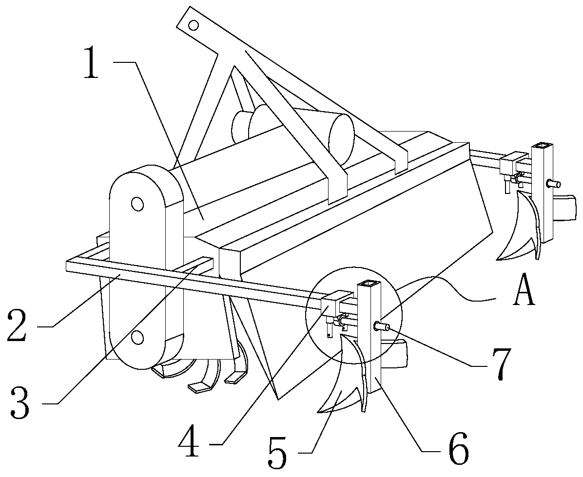
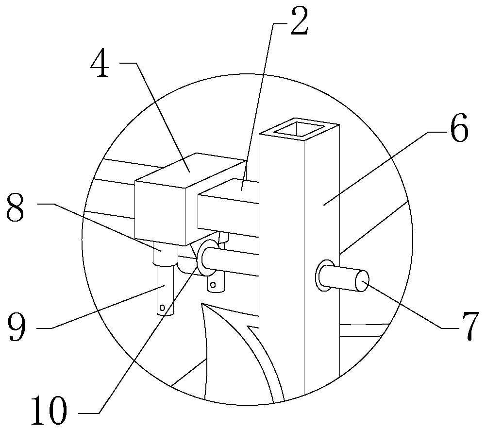
[0019] see Figure 1 to Figure 5 , the present invention provides a technical solution: a broken soil ditching device matched with a rotary tiller, comprising a rotary tiller 1, a beam 2 is provided on the side of the rotary tiller 1, and the beam 2 is close to the side of the rotary tiller 1 Two connecting rods 3 are fixed at one end, and the other end of the connecting rod 3 is fixedly connected with the rotary tiller 1, and two connecting rods 3 are installed between the beam 2 and the rotary tiller 1 to improve the stability of the installation of the beam 2.
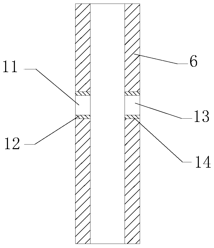
[0020] The end of the beam 2 away from the rotary tiller 1 is fixed with a square tube 6, and the lower end of the square tube 6 is fixed with a soil turning blade 5. After the rotary tiller 1 is connected with the tractor, the tractor drives the rotary tiller 1 to crush the soil, and the tractor drives the rotary tiller. During the movement of the machine 1, the rotary tiller 1 drives the soil-turning blade 5 to move, and then the soil-turning blade 5 ditches the broken soil.
[0021] A rectangular frame 4 is set on the crossbeam 2, and two retaining rods 9 are installed symmetrically on the lower end of the rectangular frame 4, and an insertion sleeve 10 is installed between the two retaining rods 9, and a first round hole 11 is opened on the side of the square tube 6 close to the crossbeam 2 The side of the square tube 6 away from the crossbeam 2 is provided with a second round hole 13 aligned with the first round hole 11, and a pin rod 7 is provided in the insertion sleeve 10, and one end of the pin rod 7 passes through the first round hole 11 and the second round hole 11. The round hole 13 extends to the side of the square tube 6 away from the beam 2. By setting the rectangular frame 4 on the beam 2 and installing two retaining rods 9 on the rectangular frame 4, if weeds and straw are entangled during the ditching process When on the square tube 6, the retaining rod 9 is between the weeds, straw and the square tube 6, and when it is necessary to clean up the weeds and straw wrapped around the square tube 6, the pin rod 7 will pass through the second round hole 13, the second A round hole 11 is inserted into the socket 10 on the rectangular frame 4, and then the pin rod 7 is hit with a tool such as a hammer, and then the rectangular frame 4 slides along the beam 2 and drives the stop rod 9 to move, thereby achieving the goal of clearing weeds and straw. The purpose is to improve the convenience of weeds and straw cleaning.
[0022] The lower end surface of the rectangular frame 4 is symmetrically fixed with two straight thread cylinders 8. At least three triangular plates are fixed on the outer surface of one end of the straight thread cylinder 8 close to the rectangular frame 4. The triangular plates are fixedly connected with the rectangular frame 4. Thread, the stop rod 9 is engaged in the straight thread barrel 8 through the external thread, and the stop rod 9 is screwed into the straight thread barrel 8 by using the external thread, which is convenient for the disassembly and assembly of the stop rod 9 and the rectangular frame 4, and is convenient for the damaged stop rod 9 is replaced, and a triangular plate is installed between the straight thread cylinder 8 and the rectangular frame 4, so as to improve the mechanical strength that the straight thread cylinder 8 is connected with the rectangular frame 4.
[0023] The outer surface of the socket 10 is fixed with a connection seat 15, and the connection seat 15 is fixedly connected with the rectangular frame 4. The connection seat 15 is installed on the socket 10 to increase the contact area between the socket 10 and the rectangular frame 4, and improve the contact area between the socket 10 and the rectangular frame 4. The stability of the connection.
[0024] Paste the first rubber ring 12 by glue in the first round hole 11, paste the second rubber ring 14 by glue in the second round hole 13, and one end of the pin rod 7 passes through the first rubber ring 12 and the second rubber ring 14 successively, During the process of inserting the pin rod 7 into the socket 10, make the pin rod 7 pass through the first rubber ring 12 and the second rubber ring 14, thereby increasing the friction coefficient between the pin rod 7 and the square tube 6, and preventing the pin rod 7 from Move around at will.
[0025] A rubber pad 16 is provided in the socket 10, and the rubber pad 16 is between the socket 10 and the pin rod 7. After the pin rod 7 is inserted in the socket 10, the rubber pad 16 is between the socket 10 and the pin rod 7. When using a tool such as a hammer to knock the pin rod 7, the rubber pad 16 plays the role of buffer protection.
[0026] Stop bar 9 is provided with pin hole away from an end outer surface of rectangular frame 4, when needing to disassemble stop bar 9, insert extension rod in the pin hole on the stop bar 9, and then be convenient to utilize extension bar to rotate stop bar 9.
[0027] Rotary tillage and ditching are completed in one operation, saving labor costs, easy mechanical disassembly, good ditching effect, and no need for manual ditch cleaning.
[0028] The above description is only a preferred embodiment of the present invention, and does not limit the present invention in any form. Although the present invention has been disclosed as above with preferred embodiments, it is not intended to limit the present invention. Anyone familiar with this field Those skilled in the art, without departing from the scope of the technical solution of the present invention, can use the technical content disclosed above to make some changes or modify equivalent embodiments with equivalent changes, but all the content that does not depart from the technical solution of the present invention, according to the present invention Any simple modifications, equivalent changes and modifications made to the above embodiments by the technical essence still belong to the scope of the technical solutions of the present invention.

PUM

no PUM

Description & Claims & Application Information

We can also present the details of the Description, Claims and Application information to help users get a comprehensive understanding of the technical details of the patent, such as background art, summary of invention, brief description of drawings, description of embodiments, and other original content. On the other hand, users can also determine the specific scope of protection of the technology through the list of claims; as well as understand the changes in the life cycle of the technology with the presentation of the patent timeline. Login to view more.
Why Eureka
Try Eureka