
A smart cleaning food processor

A food processing machine and intelligent cleaning technology, which is applied in the direction of tableware washing machine/rinsing machine, tableware washing machine/rinsing and rinsing machine parts, cleaning equipment, etc., can solve the problem of bloated crushing chamber cover structure, easy breeding of bacteria, and easy existence Cleaning dead corners and other issues

Active Publication Date: 2021-09-10
JOYOUNG CO LTD
View PDF10 Cites 0 Cited by
  • Summary
  • Abstract
  • Description
  • Claims
  • Application Information

AI Technical Summary

Problems solved by technology

[0005] In this structural scheme, a spray structure needs to be installed at the water inlet to realize the spray cleaning of the crushing chamber cover, and the spray structure can be rotated. Therefore, the cleaning structure is complicated, and the crushing chamber cover needs to have a large space to accommodate The design of the spray structure and the structure of the crushing chamber cover will be too bloated. For food processors that need to install a feeding port or a pressure relief valve on the chamber cover, it is difficult to achieve structural integration in a limited space.
And because the spray structure is horizontally protruding and arranged at the water inlet, in the process of spray cleaning, the cleaning water sprayed out by the spray structure is laterally sprayed outwards, which causes the convexity between the spray structure and the water inlet. There are likely to be cleaning dead ends at the outlet connection. When there are residual stains and residues accumulated, bacteria will easily breed if they are not cleaned for a long time, and there are hidden dangers to food hygiene and safety.
In addition, since the top of the crushing chamber cover needs a connecting pipeline extending from the top wall of the crushing chamber cover to form a water inlet, the crushing chamber cover cannot be detachably separated from the connecting pipeline and the crushing chamber, which is extremely inconvenient to disassemble

Method used


Image

  • A smart cleaning food processor
  • A smart cleaning food processor
  • A smart cleaning food processor

Examples


Embodiment 1

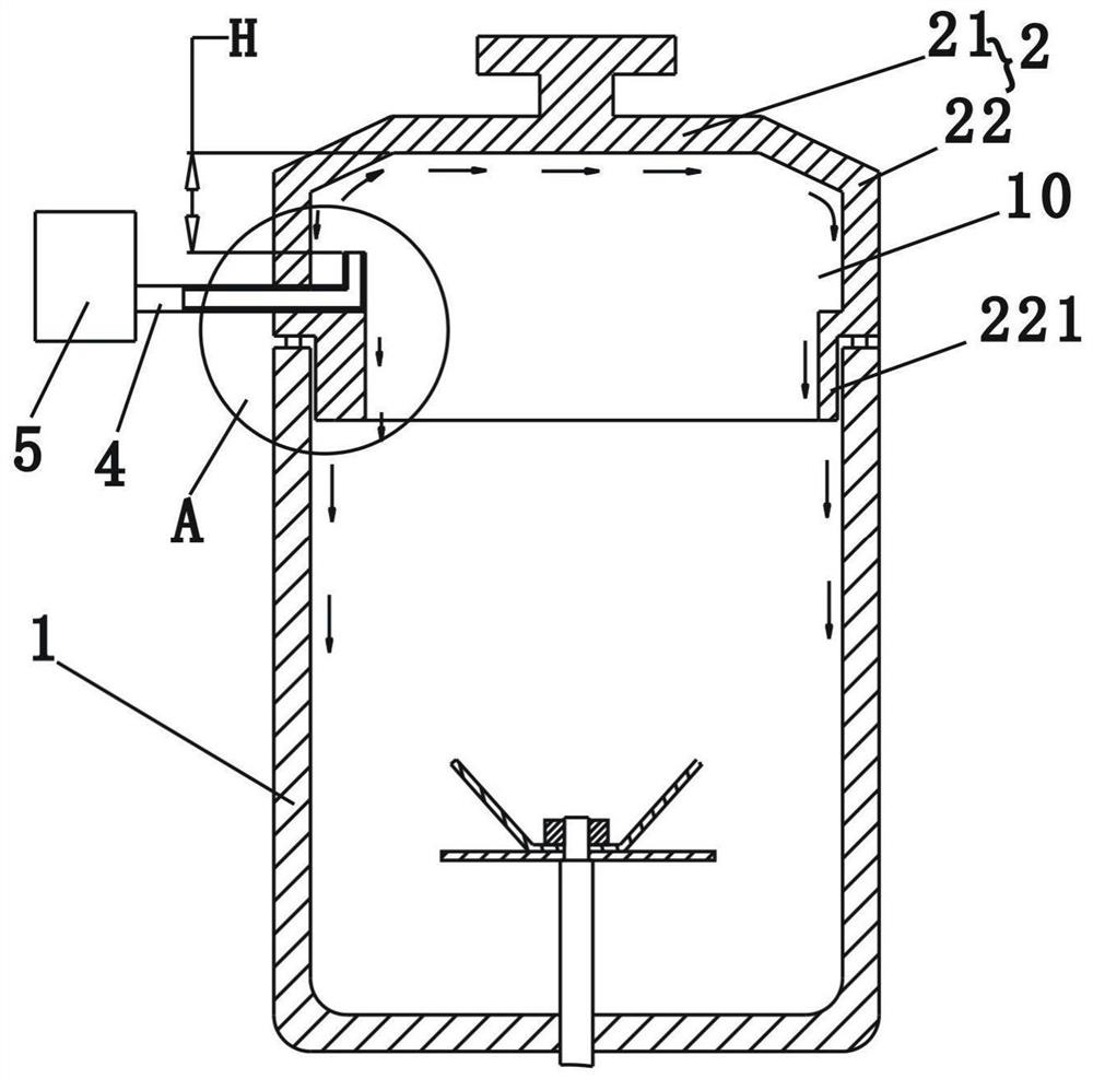
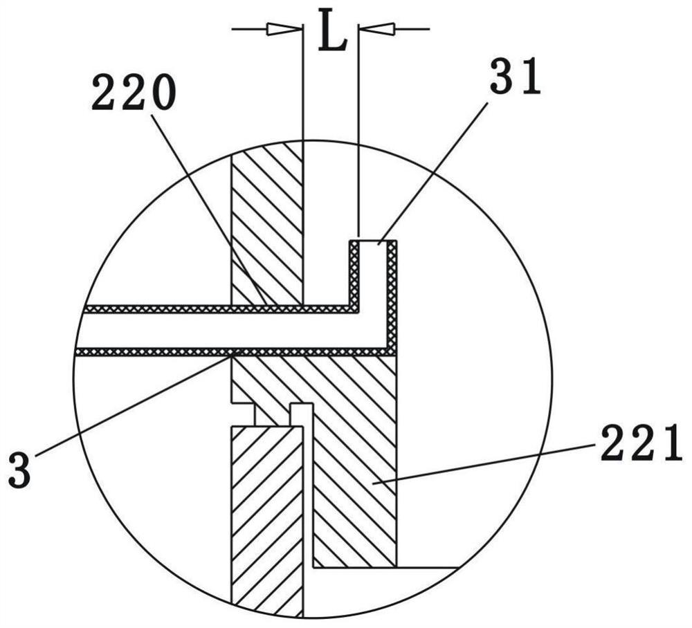
[0036] Such as figure 1 , figure 2 Shown is a schematic structural diagram of the first embodiment of the present invention. A food processor, comprising a cup body 1, a cup cover 2 mounted on the top of the cup body 1, the cup cover 2 has a top wall 21 and a peripheral wall 22 extending downward from the top wall 21, inside the cup body 1 A crushing device (not marked in the figure) for crushing materials is provided, the cup cover 2 is formed with an accommodation chamber 10, and the peripheral wall 22 of the cup cover is provided with a nozzle 3, and the nozzle 3 transversely penetrates the peripheral wall 22 of the cup cover and extend into the housing cavity 10 formed by the cup cover 2, and the nozzle 3 has an upper spout 31 arranged upwards, and the upper spout 31 sprays cleaning liquid toward the inner surface of the top wall 21 of the cup cover, and the sprayed water from the upper spout 31 The cleaning liquid washes along the inner surface of the cup cover 2, and ...

Embodiment 2

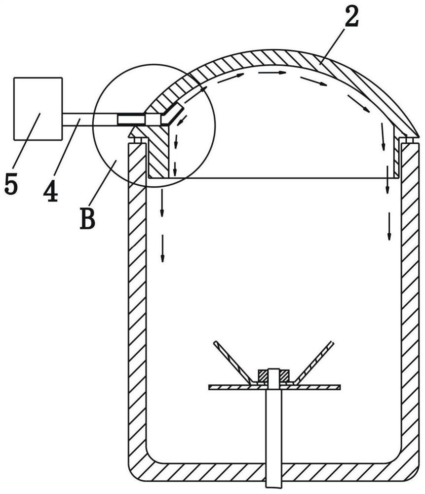
[0048] Such as image 3 , Figure 4 Shown is a schematic structural diagram of the second embodiment of the present invention. This embodiment differs from Embodiment 1 in that: in this embodiment, the inner surface contour of the cup cover 2 is spherical, and the nozzle includes a through hole 220 that runs through the wall of the cup cover 2 transversely, and the through hole 220 The water outlet is communicated with the upper nozzle 31, and the other end of the through hole 220 is communicated with the water supply system 5 through the connecting pipe 4, so that the water supply system 5 can supply water to the nozzle. Simultaneously, in the present embodiment, the upper spout 31 is close to the inner surface of the cup cover 2, and the cleaning water ejected from the upper spout 31 is sprayed obliquely relative to the vertical plane, and the spraying inclination formed by the sprayed cleaning water and the vertical plane is α1, and the angle formed by the tangent of the ...

Embodiment 3

[0053] Such as Figure 5 Shown is a schematic structural view of the third embodiment of the present invention. The difference between this embodiment and Embodiment 2 is that in this embodiment, the nozzle is a through hole 220 that runs through the cup cover laterally, and the through hole 220 is arranged obliquely toward the top of the cup cover, and the outlet end of the through hole 220 It is the upper spout 31, and, in this embodiment, the wall of the cup cover is provided with a plurality of nozzles around a circle, and the plurality of nozzles cross-spray the inner surface of the cup cover, so as to realize the full-coverage flushing and cleaning of the cup cover, and there is no cleaning blind spot.

[0054] It should be pointed out that, in this embodiment, the cup lid has a single-layer wall structure. Of course, the cup lid can also have a double-wall structure with an outer wall and an inner wall, and a cup can be formed between the outer wall and the inner wall....


PUM


Abstract

The invention relates to kitchen cooking appliances, in particular to an intelligent cleaning food processor, comprising a cup body and a cup cover mounted on the top of the cup body, a crushing device for crushing materials is arranged in the cup body, and the cup cover forms There is an accommodating cavity, and the inner wall of the cup cover is provided with a nozzle for spraying the inner surface of the cup cover, and the nozzle is located in the accommodating cavity, and it is characterized in that: the nozzle transversely penetrates the wall of the cup cover and extends into the accommodating cavity , and the water outlet end of the nozzle has an upper spout set upwards, the cleaning liquid sprayed from the upper spout washes along the inner surface of the cup cover, and washes from bottom to top to the top inner surface of the cup cover, where the upper spout is located. On the horizontal section of , the minimum horizontal distance from the edge of the upper spout to the inner surface of the lid is L, and L is not greater than 10mm. The food processing machine of the present invention has a high degree of intelligence, can realize automatic cleaning of the cup cover and the inner surface of the cup, and there is no cleaning dead angle.

Description

technical field [0001] The invention relates to kitchen cooking appliances, in particular to an intelligent cleaning food processor. Background technique [0002] Existing home kitchens have cooking utensils with lids, such as electric rice cookers, electric pressure cookers, soybean milk makers with motors under the structure, food processors, etc., which need to be manually cleaned by the user after making food, which is troublesome to clean. [0003] Moreover, in the process of using the cooking utensil to cook food, the heated soup will generate foam and continuously impact the cover of the cooking utensil, causing more residues and stains to remain on the cover. Especially for a food processor with a crushing device, the crushing device will drive the slurry to continuously rotate at high speed during the whipping process, and the whipped material and slurry will also splash onto the cover, which will easily cause the cover The body retains pulp residue or pulp stains....

Claims


Application Information

Patent Timeline
Patent Type & Authority Patents(China)
IPC IPC(8): A47J27/00A47J36/00A47J43/04A47J43/07A47L15/00A47L15/16A47L15/42
CPCA47J27/002A47J36/00A47J43/04A47J43/07A47L15/0065A47L15/16A47L15/42A47L15/4278
Inventor 王旭宁张文凡
Owner JOYOUNG CO LTD
Learn More