
An automatic fixture that can be lifted and rotated for precision parts processing

A technology for lifting and rotating precision parts, applied in the direction of manufacturing tools, metal processing equipment, metal processing machinery parts, etc., can solve the problems such as the decline of rotation accuracy, affecting the processing accuracy, and increasing the size, to improve the lifting accuracy and ensure the accuracy. , the effect of reducing damage

Active Publication Date: 2021-03-30
株洲达睿精密制造有限公司
View PDF10 Cites 0 Cited by
  • Summary
  • Abstract
  • Description
  • Claims
  • Application Information

AI Technical Summary

Problems solved by technology

[0002] At present, when processing large-scale workpieces, especially heavy-duty workpieces, they are generally fixed on the rotary table by using machine fixtures. , At present, for this kind of fixture, the bearing is generally used to support the rotation, and the movement of the nut screw is used to realize the lifting of the table. In this way, for heavy workpieces, only relying on the bearing for rotational support, it is easy Abrasion occurs, resulting in a decrease in the accuracy of rotation. When lifting, the gravity of the workpiece is completely supported by the nut screw, which leads to faster damage to the nut screw. With use, the pitch of the screw becomes larger, which leads to After lifting and lowering, the error of tool setting and other problems will increase, which will greatly reduce the subsequent machining accuracy and affect the machining accuracy.

Method used


Image

  • An automatic fixture that can be lifted and rotated for precision parts processing
  • An automatic fixture that can be lifted and rotated for precision parts processing
  • An automatic fixture that can be lifted and rotated for precision parts processing

Examples


Embodiment Construction

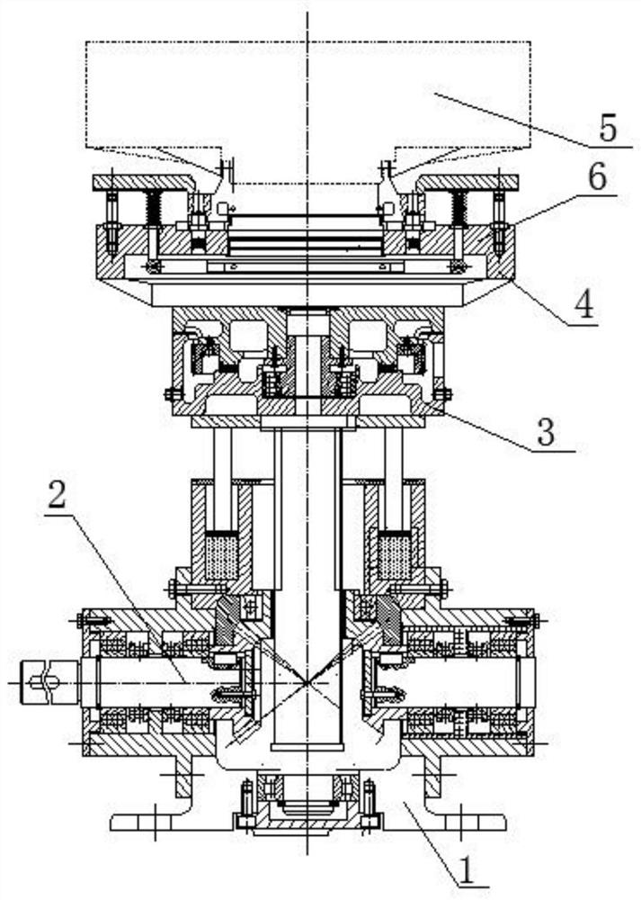
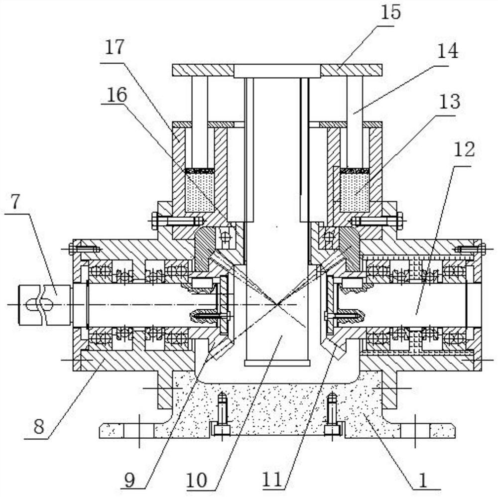
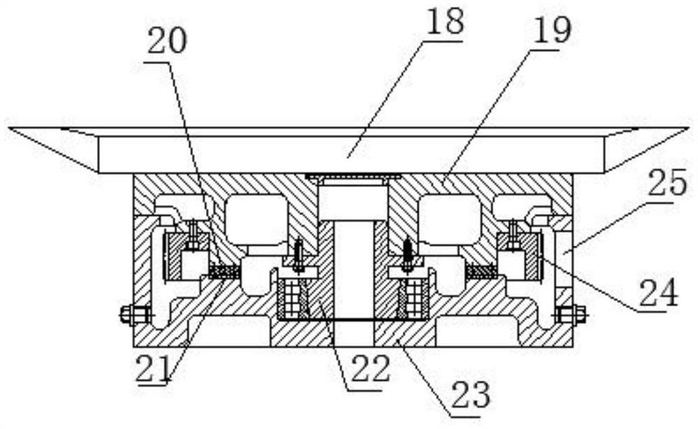
[0024] see Figure 1~4 , in an embodiment of the present invention, an automatic fixture that can be lifted and rotated for precision parts processing, it is used for clamping and fixing a heavy workpiece 5, and it includes a base 1, a lifting mechanism 2, a rotating mechanism 3, and a clamping table 4 and a clamping and positioning mechanism 6, wherein, the base 1 is fixedly connected with an elevating mechanism 2, the output end of the elevating mechanism 2 is connected with the rotating mechanism, and the output end of the rotating mechanism is connected with the clamping platform , the clamping platform is provided with a clamping and positioning mechanism 6 for clamping and fixing the workpiece 5; it is characterized in that the lifting mechanism 2 includes a precision screw drive lifting mechanism, a hydraulic support mechanism and a lifting platform 15, wherein the The precision screw driving lifting mechanism is arranged in the driving box 8, and the driving box is arr...


PUM


Abstract

The invention relates to the technical field of fixtures for precision part processing, in particular to an automatic fixture capable of lifting and rotating for precision part processing. According to the automatic fixture, a hydraulic support mechanism is arranged on a precision screw drive lifting mechanism, upward support force is provided for a lifting platform through the hydraulic support mechanism, in this way, driving force of a thread of the precision screw drive lifting mechanism can be effectively reduced, the damage to the thread is reduced, the accuracy of thread drive is effectively ensured, and the problem of low accuracy only using a hydraulic cylinder to lift is solved; and the support force of the hydraulic support mechanism is less than gravity of a heavy workpiece, thestroke can be effectively controlled by the precision screw drive lifting mechanism, a control mechanism enables the hydraulic support mechanism to follow the precision screw drive lifting mechanismto move, thus the precision screw drive lifting mechanism controls the driving quantity of lifting to make the support force of the hydraulic support mechanism to the lifting platform remain unchangedas far as possible, and the lifting accuracy is improved.

Description

technical field [0001] The invention relates to the technical field of clamps for precision parts processing, in particular to an automatic clamp for precision parts processing that can be lifted and rotated. Background technique [0002] At present, when processing large-scale workpieces, especially heavy-duty workpieces, they are generally fixed on the rotary table by using machine fixtures. , At present, for this kind of fixture, the bearing is generally used to support the rotation, and the movement of the nut screw is used to realize the lifting of the table. In this way, for heavy workpieces, only relying on the bearing for rotational support, it is easy Abrasion occurs, resulting in a decrease in the accuracy of rotation. When lifting, the gravity of the workpiece is completely supported by the nut screw, which leads to faster damage to the nut screw. With use, the pitch of the screw becomes larger, which leads to After lifting and lowering, the errors in tool settin...

Claims


Application Information

Patent Timeline
Patent Type & Authority Patents(China)
IPC IPC(8): B23Q1/26B23Q3/08
CPCB23Q1/26B23Q3/082
Inventor 郭瑞瑞曹福来张星袁培佩
Owner 株洲达睿精密制造有限公司
Learn More