Elastic and adaptive touch joint mechanism

An adaptive and elastic technology, applied in the field of EPP production, can solve the problems of production process impact and waste, and achieve the effect of enhancing strength, reducing waste and avoiding leakage

Pending Publication Date: 2020-02-11
杭州塑团机械有限公司
View PDF0 Cites 0 Cited by
  • Summary
  • Abstract
  • Description
  • Claims
  • Application Information

AI Technical Summary

Problems solved by technology

[0002] EPP is a highly crystalline polymer with excellent shock resistance and strong recovery ability after deformation. It is extremely light in weight. On the basis of ensuring strength, it can greatly reduce product quality. Packaging materials for electronic products, automobile bumpers, shock-proof cores, sports shoes soles and many other fields are being used more and more widely. EPP should be stored in a constant pressure environment, such as inside a pressure-holding barrel. During production, the EPP is introduced into the mold. The current mainstream import method is to touch the discharge end of the pressure-holding barrel with the feed end of the moving mold and the solid mold, and pass through the discharge side and the feed side one by one. Corresponding interface, EPP is introduced into the mold, and the structure that completes the collision action is the collision plate. Under the premise of ensuring the one-to-one correspondence of the interface, the collision plate on the discharge side moves to the collision plate on the feed side. Until the two contact plates are in close contact, but due to inevitable processing errors, there will always be gaps between the contact plates, and the particle size of EPP is relatively small. Falling inside the gap between the bumper plates is not only wasteful, but also makes the user have to do extra cleaning work, which affects the normal production process, so urgent changes are needed

Method used


Image

  • Elastic and adaptive touch joint mechanism
  • Elastic and adaptive touch joint mechanism
  • Elastic and adaptive touch joint mechanism

Examples


Embodiment Construction

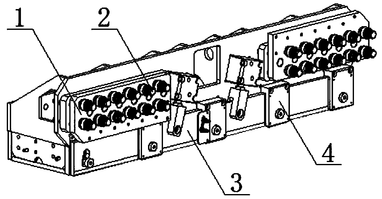
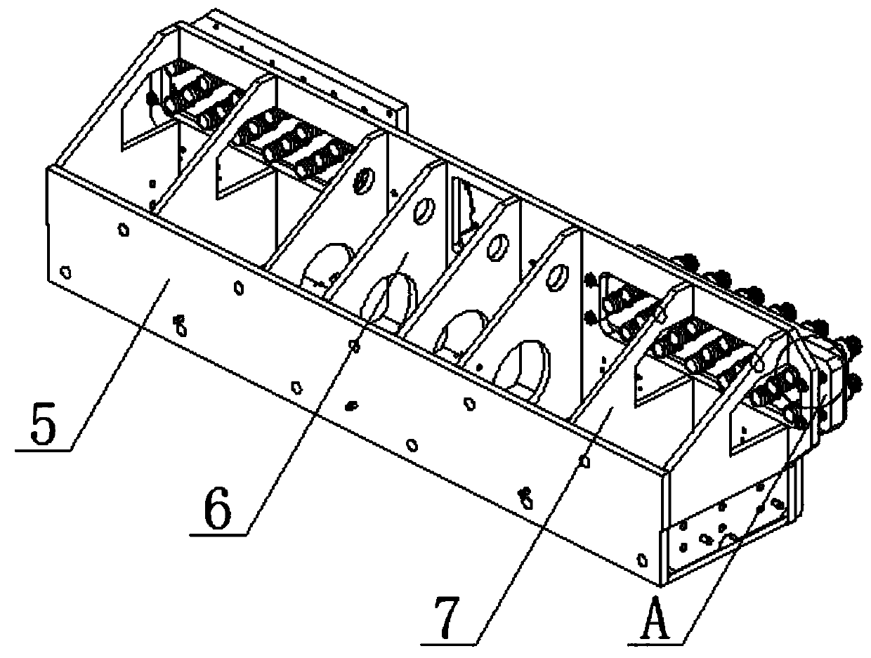
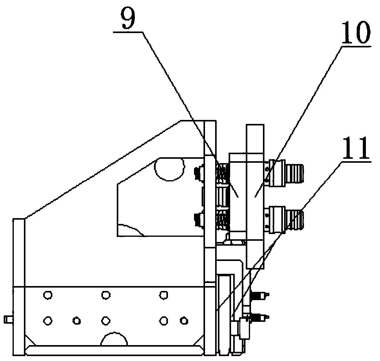
[0026] In order to make the description more clear, in combination with the accompanying drawings of the description Figure 1 to Figure 6 , to further describe an elastic self-adaptive collision mechanism of the present invention.

[0027] An elastic self-adaptive bumping mechanism, comprising a quick lock frame 5, characterized in that: the upper part of one side of the quick lock frame 5 is provided with a bumping part 1, and the bumping part 1 includes a discharge bumping plate 10, a feeding Collision plate 9, the discharge collapsing plate 10 is arranged parallel to the feeding colliding plate 9, and the feeding collapsing plate 9 is located between the quick lock frame 5 and the discharging collapsing plate 10 Between, the surface of the discharge bumping plate 10 and the feed bumping plate 9 are provided with through holes and the through holes correspond one by one, the discharge bumping plate 10 is far away from the feeding bumping plate 9 The discharge joint 2 is mo...


PUM


Abstract

The invention discloses an elastic and adaptive touch joint mechanism and belongs to the technical field of EPP production. The touch joint mechanism comprises a rapid locking frame and is characterized in that a touch joint part is arranged at the upper part of one side of the rapid locking frame, the touch joint part comprises a discharging touch joint plate and a feeding touch joint plate, thedischarging touch joint plate and the feeding touch joint plate are arranged in parallel, the feeding touch joint plate is located between the rapid locking frame and the discharging touch joint plate, through holes are arranged in the surfaces of the discharging touch joint plate and the feeding touch joint plate and are in one-to-one correspondence, a discharging joint is movably arranged in theside, far from the feeding touch joint plate, of the discharging touch joint plate and at the positions of the through holes, a feeding hose threaded joint is movably arranged in the side, far from the discharging touch joint plate, of the feeding touch joint plate and at the positions of the through holes, a locating screw is arranged on the surface of the rapid locking frame, the locating screwis connected with the feeding touch joint plate through threads, and a spring is arranged on the surface of the locating screw. The problem that leakage often occurs in the process that EPP is discharged in the current main flow discharging mode is solved.

Description

technical field [0001] The invention relates to the technical field of EPP production, in particular to an elastic self-adaptive bumping mechanism. Background technique [0002] EPP is a highly crystalline polymer with excellent shock resistance and strong recovery ability after deformation. It is extremely light in weight. On the basis of ensuring strength, it can greatly reduce product quality. Packaging materials for electronic products, bumpers of automobiles, shockproof cores, soles of sports shoes and many other fields are being used more and more widely. EPP should be stored in a constant pressure environment, such as inside a pressure-holding barrel. During production, the EPP is introduced into the mold. The current mainstream import method is to touch the discharge end of the pressure-holding barrel with the feed end of the moving mold and the solid mold, and pass through the discharge side and the feed side one by one. Corresponding interface, EPP is introduced i...

Claims


Application Information

Patent Timeline
IPC IPC(8): B29C44/38B29C44/44
CPCB29C44/38B29C44/385B29C44/445
Inventor 钟志鹏吴晓会
Owner 杭州塑团机械有限公司
Why Eureka
Try Eureka