Aircraft stage separation structure and method

A technology for inter-stage separation and aircraft, applied in the field of aircraft separation, can solve problems such as not having rapid separation, achieve simple and reasonable structure, improve stability, and reduce disturbance

Active Publication Date: 2020-02-11
SHANGHAI INST OF ELECTROMECHANICAL ENG
View PDF7 Cites 3 Cited by
  • Summary
  • Abstract
  • Description
  • Claims
  • Application Information

AI Technical Summary

Problems solved by technology

Although this scheme has a simple structure, it cannot avoid the instability caused by the disturbing torque generated by the projectile disturbance during separation, and it does not have the characteristics of rapid separation.

Method used


Image

  • Aircraft stage separation structure and method
  • Aircraft stage separation structure and method
  • Aircraft stage separation structure and method

Examples


Embodiment Construction

[0033] The present invention will be described in detail below in conjunction with specific embodiments. The following examples will help those skilled in the art to further understand the present invention, but do not limit the present invention in any form. It should be noted that those skilled in the art can make several changes and improvements without departing from the concept of the present invention. These all belong to the protection scope of the present invention.

[0034] In the description of this application, it should be understood that the terms "upper", "lower", "front", "rear", "left", "right", "vertical", "horizontal", "top", The orientation or positional relationship indicated by "bottom", "inner", "outer", etc. is based on the orientation or positional relationship shown in the drawings, and is only for the convenience of describing the application and simplifying the description, rather than indicating or implying the referred device Or elements must hav...


PUM


Abstract

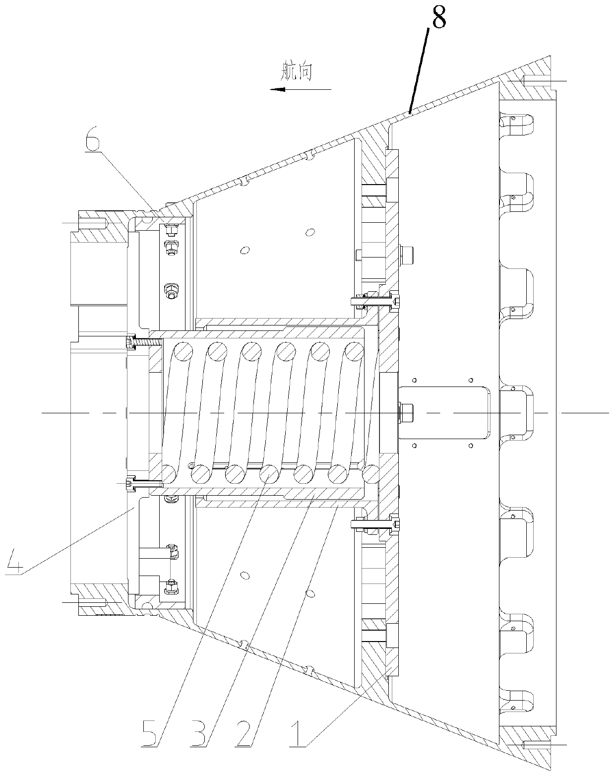
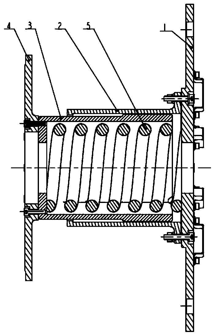
The invention provides an aircraft stage separation structure and method. The structure comprises an interstage cabin, a spring separation mechanism and a cutting rope assembly. The two ends of the interstage cabin are connected with a booster stage and an aircraft main stage. The spring separation mechanism comprises a bottom plate, an outer sleeve, an inner sleeve, a force bearing plate and a spring. The cutting rope assembly comprises a cutting rope, an electric ignition tube and a flame detonator. The bottom plate is connected with the outer sleeve, the force bearing plate is connected with the inner sleeve, the outer sleeve is mounted on the outer portion of the inner sleeve in a sleeving manner, and the spring is mounted in the inner sleeve. The bottom plate is connected with one endof the interstage cabin, and the force bearing plate is connected with the other end of the interstage cabin. The electric ignition tube and the flame detonator are arranged on the cutting rope, theelectric ignition tube is connected with the flame detonator, and the cutting rope is arranged on the interstage cabin. The structure is simple and reasonable, the connecting constraint between the booster stage and the aircraft main stage is relieved through the cutting rope assembly, meanwhile, the constraint of the spring separation mechanism is also relieved, spring force releases elastic force to push away the booster stage and the aircraft main stage, and the booster stage and the aircraft main stage are separated rapidly.

Description

technical field [0001] The invention relates to the technical field of aircraft separation, in particular to an aircraft inter-stage separation structure and method. Background technique [0002] At present, long-range air defense missiles are generally improved designs based on mature missile platforms, and mainly meet the requirements of long-range air defense by adding a new level of booster. Therefore, missiles generally adopt the overall plan of "main stage + booster". The booster engine is separated from the main-stage missile after its work is completed. Before the separation, the missile is statically stable; after separation, the main-stage body of the missile is statically unstable; when the separation occurs, the flight Mach number of the missile is around 2.3 to 2.6. The characteristics of the missile body change from static stability to static instability in a short period of time before and after separation, and the disturbance torque generated by the disturban...

Claims


Application Information

Patent Timeline
Patent Type & Authority Applications(China)
IPC IPC(8): F42B15/36
CPCF42B15/36Y02T50/40
Inventor 刘劲松胡洁康海峰孙文钊蒋君庭江玉刚曾清香施臣钢
Owner SHANGHAI INST OF ELECTROMECHANICAL ENG
Why Eureka
Try Eureka