
A Hybrid Circuit Breaker Topology System for AC Capacitive Load Switching

A hybrid circuit breaker and capacitive load technology, which is applied in the field of hybrid circuit breaker topology system, can solve the problems of circuit breaker refusal to break short-circuit current, low service life of circuit breaker, ablation of contact surface, etc. quality, prolong service life, and improve the effect of breaking capacity

Active Publication Date: 2020-09-25
GUANGDONG POWER GRID CO LTD +1
View PDF6 Cites 1 Cited by
  • Summary
  • Abstract
  • Description
  • Claims
  • Application Information

AI Technical Summary

Problems solved by technology

[0007] In order to overcome the existing power switching equipment used in the field of reactive power compensation in power systems, such as SF6 circuit breakers, during frequent reactive power compensation switching operations, the contact surface is easily ablated by inrush arcs, resulting in low service life of the circuit breaker, or even In case of major accidents that cause the circuit breaker to refuse to operate or fail to break the short-circuit current, the present invention proposes a hybrid circuit breaker topology system for AC capacitive load switching. The degree of ablation of the contacts of the circuit breaker, prolonging the service life, and improving the breaking quality and reliability of the circuit breaker used for reactive power compensation of the power system

Method used


Image

  • A Hybrid Circuit Breaker Topology System for AC Capacitive Load Switching
  • A Hybrid Circuit Breaker Topology System for AC Capacitive Load Switching
  • A Hybrid Circuit Breaker Topology System for AC Capacitive Load Switching

Examples


Embodiment 1

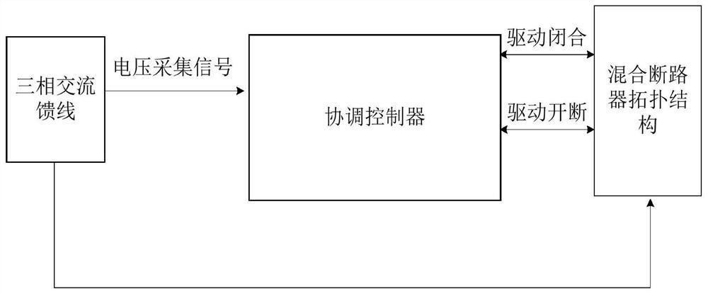
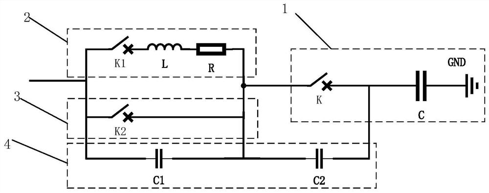
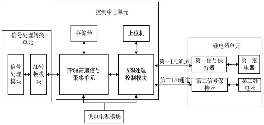
[0039] Such as figure 1 The structural connection block diagram of the hybrid circuit breaker topology system for AC capacitive load switching is shown, see figure 1 , a hybrid circuit breaker topology system for AC capacitive load switching, characterized in that the system includes a three-phase AC feeder, a hybrid circuit breaker topology, and is used to control the hybrid circuit breaker topology to complete the opening and closing action There are multiple circuit breakers in the hybrid circuit breaker topology, the coordination controller is connected to the three-phase AC feeder, collects and analyzes the voltage amplitude and phase signal of the three-phase AC feeder, and the three-phase AC The feeder is connected to the hybrid circuit breaker topology, and the operation of the hybrid circuit breaker topology is supported by the three-phase AC feeder voltage; the coordination controller is bidirectionally connected to the hybrid circuit breaker topology, and the coordi...


PUM


Abstract

The invention provides a hybrid circuit breaker topology system used for alternating-current capacitive load switching. The system comprises a three-phase alternating-current feeder line, a hybrid circuit breaker topology structure and a coordination controller, wherein the coordination controller is connected with the three-phase alternating-current feeder line, collects, analyzes and processes avoltage amplitude and a phase signal of the three-phase alternating-current feeder line, the three-phase alternating-current feeder line is connected with the hybrid circuit breaker topology structure, and operation of the hybrid circuit breaker topology structure is supported through a voltage of the three-phase alternating-current feeder line; and the coordination controller is in bidirectionalconnection with the hybrid circuit breaker topology structure, and the coordination controller uses an acquired three-phase alternating-current feeder line voltage amplitude and the phase signal to drive the hybrid circuit breaker topology structure to carry out on-off closing phase selection action, and receives an on-off closing signal fed back by the hybrid circuit breaker topology structure.In the invention, the coordination controller coordinates and controls on-off closing cooperation action between hybrid circuit breakers so as to reduce an ablation degree of circuit breaker contacts,prolong a service life of the circuit breaker which is applied to the alternating-current capacitive load switching, and improve reliability.

Description

technical field [0001] The present invention relates to the technical field of AC capacitive load switching, and more specifically, to a hybrid circuit breaker topology system for AC capacitive load switching. Background technique [0002] The power system is an instant balance system. Due to the existence of capacitive loads and inductive loads, a large amount of reactive power will be generated during the operation of the system, and the reactive power will cause the voltage of the power system to deviate and cause losses. In order to ensure the power system Normal operation requires reactive power compensation. According to the operating experience of the power system, for every 1kW of active power generated, 1.2-1.4kvar of reactive power needs to be compensated to maintain the normal working voltage of the power system. [0003] Switching capacitor bank is a simple and economical method to generate reactive power, and is widely used in power systems with voltage levels ...

Claims


Application Information

Patent Timeline
Patent Type & Authority Patents(China)
IPC IPC(8): H02J3/18
CPCH02J3/1821Y02E40/30
Inventor 陈道品金向朝武利会张乾良谭劲章陈邦发陈斯翔黄静何子兰陈贤熙
Owner GUANGDONG POWER GRID CO LTD
Learn More