
Scarifier

A technology of scarifier and driving mechanism, which is applied in the fields of tillage implements, agricultural machinery and implements, etc. It can solve the problems of large volume and weight of the whole machine, complex assembly of the whole machine, large size of worm gear reducer, etc., and achieve compact structure Convenience, ease of structure, and ease of use

Pending Publication Date: 2020-02-14
SUZHOU KINGCLEAN PRECISION MACHINERY
View PDF0 Cites 1 Cited by
  • Summary
  • Abstract
  • Description
  • Claims
  • Application Information

AI Technical Summary

Problems solved by technology

[0002] At present, the scarifiers on the market use motors connected with worm gear reducers through flexible shafts, and the vertical rotation of the motor is reversed to parallel horizontal blade rotation. The size of the worm gear reducer is large, the volume and weight of the whole machine are correspondingly large, and the assembly of the whole machine is complicated.

Method used


Image

  • Scarifier
  • Scarifier
  • Scarifier

Examples


Embodiment Construction

[0029] The above solution will be further described below in conjunction with specific embodiments. It should be understood that these examples are used to illustrate the present invention and not to limit the scope of the present invention. The implementation conditions used in the examples can be further adjusted according to the conditions of specific manufacturers, and the implementation conditions not indicated are usually the conditions in routine experiments.

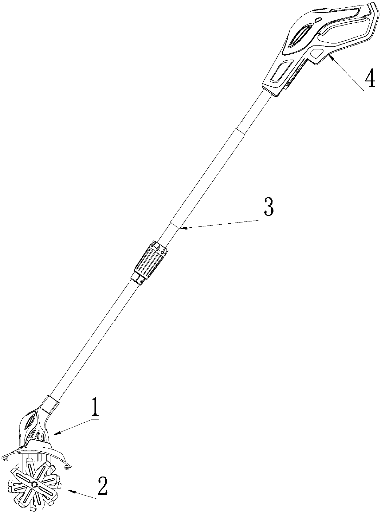
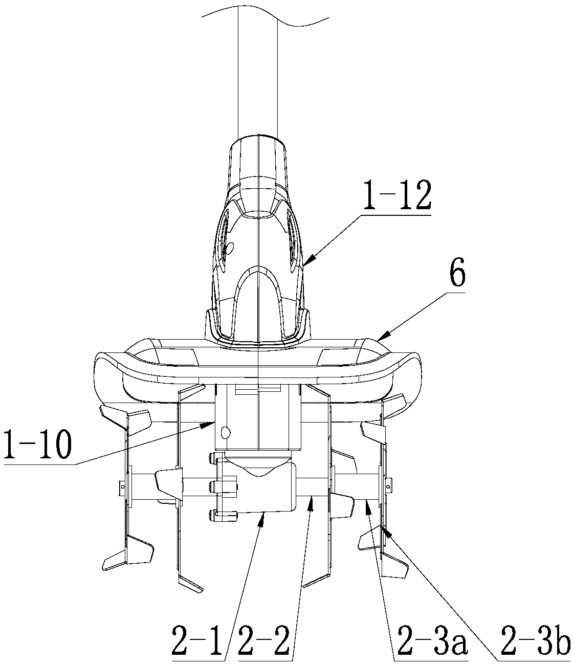
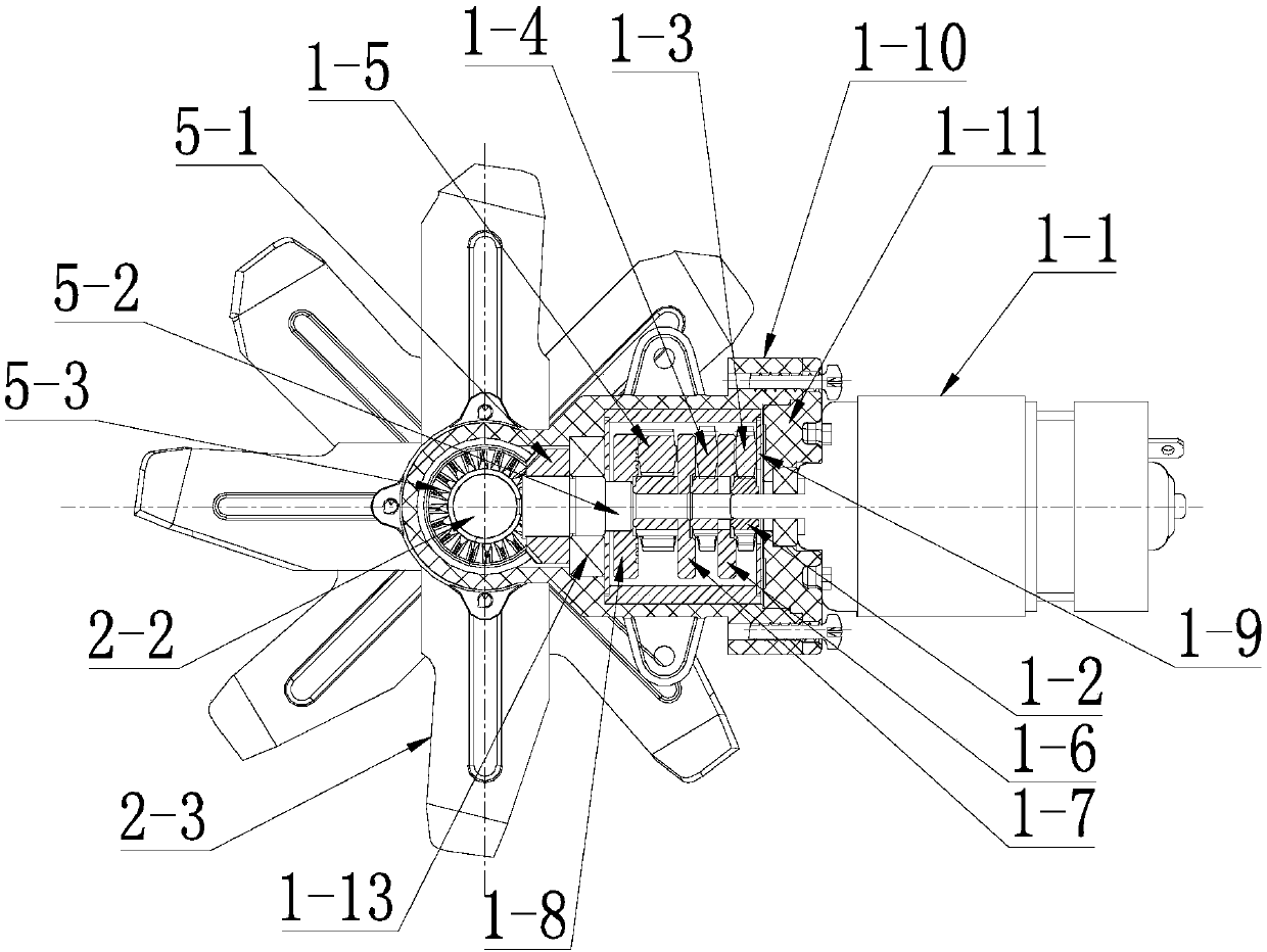
[0030] see Figure 1-2 , is a structural schematic diagram of an embodiment of the present invention, providing a scarifier, including a driving mechanism 1, a scarifying mechanism 2, a push rod 3, and a handle 4, wherein the driving mechanism 1 mechanism is accommodated in a casing 1-12, and the push rod 3. The lower end is connected to the shell 1-12, and the upper end of the push rod 3 is connected to the handle 4. The driving mechanism 1 is used to drive the loosening mechanism 2 to complete the loosening ac...


PUM


Abstract

The invention discloses a scarifier, which comprises a driving mechanism (1) and a scarifying mechanism (2). The scarifying mechanism (2) is in transmission connection with the driving mechanism (1) through a bevel gear component (5) to convert a radial torque into an axial torque. The scarifier has advantages of compact structure and convenience in use.

Description

technical field [0001] The invention relates to the technical field of garden tools, in particular to a scarifier. Background technique [0002] The rippers currently on the market use a motor connected to a worm worm gearbox through a flexible shaft, and the vertical rotation of the motor is reversed into a parallel horizontal plane blade rotation. The size of the worm worm gearbox is large, the volume and weight of the whole machine are correspondingly large, and the assembly of the whole machine is complicated. Contents of the invention [0003] The object of the present invention is to provide a scarifier which is compact in structure and easy to use. [0004] Based on the above problems, the technical solution provided by the invention is: [0005] The scarifier includes a driving mechanism and a scarifying mechanism, and the scarifying mechanism is connected to the driving mechanism through a bevel gear assembly to convert radial torque into axial torque. [0006] ...

Claims


Application Information

Patent Timeline
Patent Type & Authority Applications(China)
IPC IPC(8): A01B33/08A01B33/10A01B33/14
CPCA01B33/08A01B33/082A01B33/103A01B33/142
Inventor 倪祖根
Owner SUZHOU KINGCLEAN PRECISION MACHINERY
Learn More