Bending process and bending equipment for elevator sill

A sill and elevator technology, which is applied to metal processing equipment, elevators in buildings, manufacturing tools, etc., can solve the problems of lower production efficiency, welding troubles, and defective products, so as to reduce the rate of defective products and improve production efficiency Effect

Active Publication Date: 2020-12-15
浙江君菱机电科技有限公司
View PDF10 Cites 0 Cited by
  • Summary
  • Abstract
  • Description
  • Claims
  • Application Information

AI Technical Summary

Problems solved by technology

However, during welding, because the length of the elevator sill is relatively long, the worker cannot quickly and conveniently locate the guide 13 when holding the guide 13 for welding, and it is easy to cause the position of the guide 13 to shift during the welding process. , resulting in defective products
And it is also very troublesome when welding, which takes a long time and reduces production efficiency

Method used


Image

  • Bending process and bending equipment for elevator sill
  • Bending process and bending equipment for elevator sill
  • Bending process and bending equipment for elevator sill

Examples


Embodiment Construction

[0036] The present invention will be described in further detail below in conjunction with the accompanying drawings.

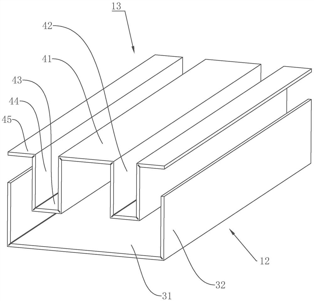
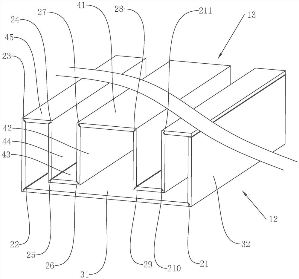
[0037] refer to figure 2 and image 3 , which is a bending process for an elevator sill disclosed by the present invention, comprising the following steps:

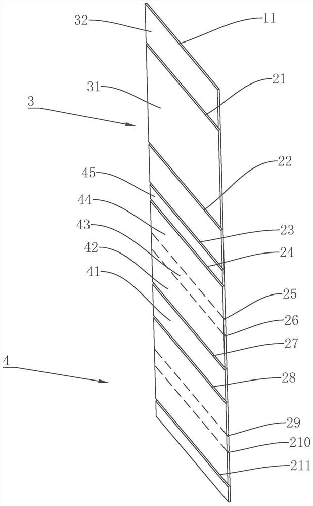
[0038] Step 1: plate cutting, the raw material plate is cut by a cutting machine to form a rectangular plate to be processed 1;

[0039] Step 2: Create folding grooves. A total of eleven folding grooves are opened on the upper surface and the lower surface of the plate 1 to be processed by the milling cutter. One side of the plate 1 to be processed is called a plate edge 11, each The folding grooves are all parallel to the sheet edge 11, and the folding grooves are V-shaped grooves. The folding grooves are named as the first groove 21, the second groove 22, the third groove 23, the second groove from the sheet edge 11 to the side away from the sheet edge 11, Four grooves 24, the fifth groove 25, the ...


PUM


Abstract

The invention relates to a bending process and bending equipment of an elevator sill. The bending process comprises the steps of cutting a plate to be machined, forming a bending groove in the plate to be machined, bending the plate to be machined to form a base piece and a guide piece and bending the plate to be machined through the bending equipment. An elevator sill body can be produced quicklyand precisely; a defective rate of the elevator sill is reduced; and the production efficiency is improved.

Description

technical field [0001] The invention relates to the technical field of elevator accessories, in particular to an elevator sill bending process and bending equipment thereof. Background technique [0002] The elevator sill is installed between the vertical elevator doors, and plays a guiding role in the operation of the elevator car doors and landing doors. as attached figure 1 As shown, the elevator sills of today generally consist of a base member 12 and a guide member 13 . The base member 12 includes a first bottom plate 31 , opposite sides of the first bottom plate 31 are folded toward the same vertical side to form a second bottom plate 32 , and the two second bottom plates 32 are parallel to each other. The guide 13 includes a first guide plate 41 , a second guide plate 42 , a third guide plate 43 , a fourth guide plate 44 and a fifth guide plate 45 . The second guide plate 42 is provided with two pieces, and is arranged along two opposite sides of the first guide pl...

Claims


Application Information

Patent Timeline
Patent Type & Authority Patents(China)
IPC IPC(8): B21D5/01B21D43/00B23P15/00B66B13/30
CPCB21D5/002B21D5/01B23P15/00B66B13/301
Inventor 钱文龙朱海山孙金龙吴琪琪杨时勇张志敏
Owner 浙江君菱机电科技有限公司
Why Eureka
Try Eureka