Annular multiple node type welding device based on electromechanical control and use method thereof

A welding device and electromechanical control technology, applied in auxiliary devices, welding equipment, auxiliary welding equipment, etc., can solve the problems of wasting manpower, difficult circular multi-point welding, and reducing work efficiency, so as to improve automatic operation and improve the flexibility of electric welding Performance and efficiency, the effect of improving the support effect

Inactive Publication Date: 2020-02-14
JIANGSU MICFIRST AUTOMATION TECH
View PDF5 Cites 8 Cited by
  • Summary
  • Abstract
  • Description
  • Claims
  • Application Information

AI Technical Summary

Problems solved by technology

However, the general direction of the welding device in the prior art is often fixed, and it is difficult to realize circular multi-point welding, and after the steel member is limited, if it is disassembled and then repositioned to realize welding at other parts, then Waste of manpower and reduce work efficiency to a certain extent

Method used


Image

  • Annular multiple node type welding device based on electromechanical control and use method thereof
  • Annular multiple node type welding device based on electromechanical control and use method thereof
  • Annular multiple node type welding device based on electromechanical control and use method thereof

Examples


Embodiment 1

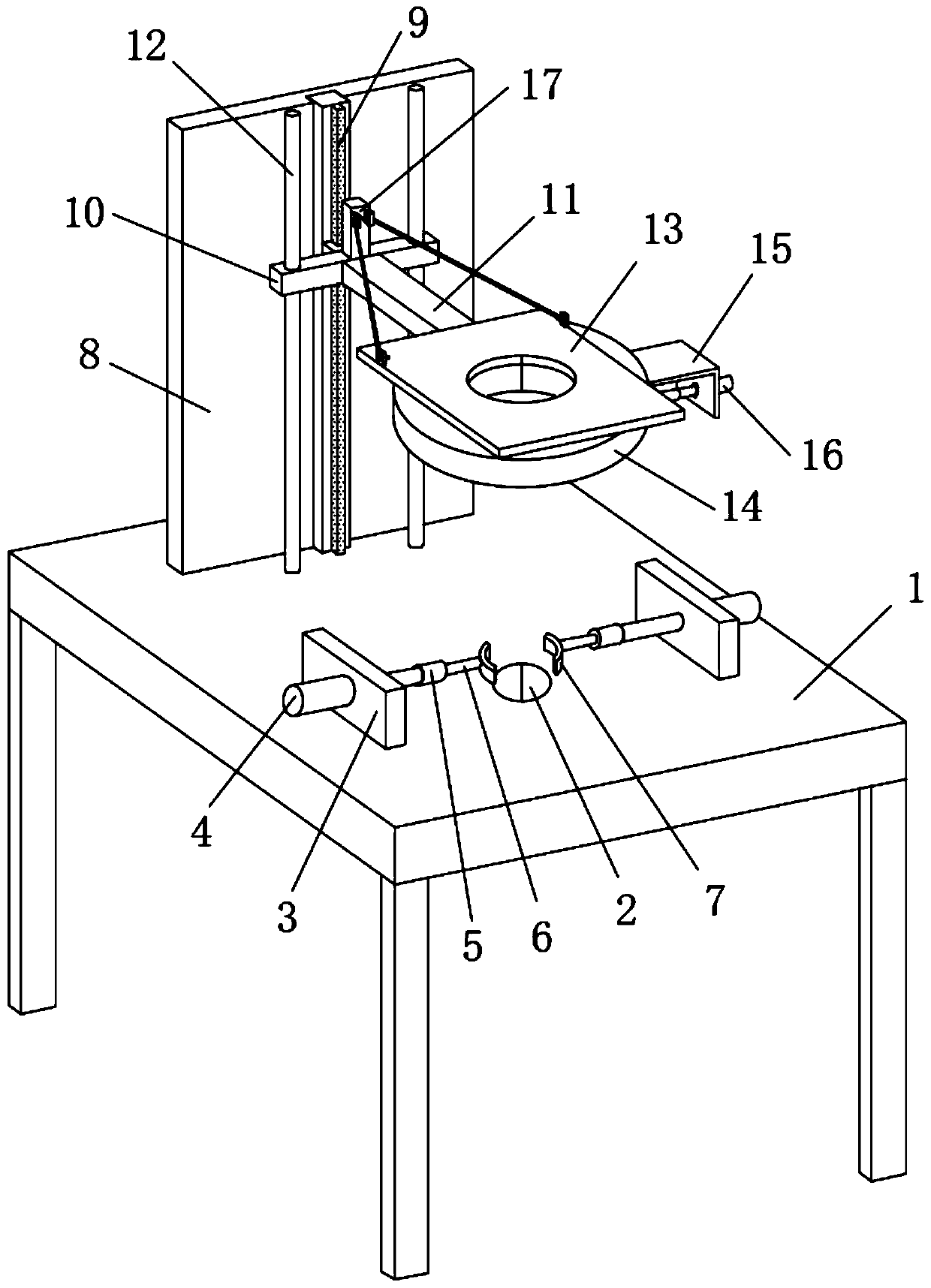
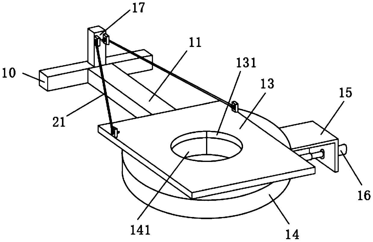
[0039] see figure 1 and Figure 5 , a ring-shaped multi-node welding device based on electromechanical control, including an operating table 1, a workpiece sleeve hole 2 is opened in the middle of the front end of the operating table 1, and the workpiece sleeve hole 2 is used to sleeve the workpiece steel pipe. 1. The two sides of the front end are fixedly equipped with workpiece limit mechanisms symmetrically arranged on both sides of the workpiece sleeve hole 2. A pair of workpiece limit mechanisms realize the limit and fixation of the workpiece to be welded. The fixed plate 3, the outer wall of the fixed plate 3 is fixedly connected with an electric push rod 4, the telescopic end of the electric push rod 4 runs through the fixed plate 3 and is fixedly connected with a workpiece limit block 7, a pair of workpiece limit blocks 7 are in a The electric push rods 4 are pushed closer to each other to clamp and limit the workpiece, and the workpiece limit block 7 can be replaced ...


PUM


Abstract

The invention discloses an annular multiple node type welding device based on electromechanical control and a use method thereof, and belongs to the electromechanical welding technology field. The annular multiple node type welding device based on the electromechanical control comprises an operation table, wherein a workpiece sleeving hole is formed in the middle of the front end of the operationtable. The annular multiple node type welding device based on the electromechanical control and the use method thereof clamp and fix the workpiece to be welded through a pair of workpiece limiting mechanisms, then drive an annular electric welding mechanism at the bottom end of the round operation table to press down until the position, to be welded, on the workpiece, through an electric sliding rail, can weld the welding position through the annular electric welding mechanism, can weld welding points on an annular part of the workpiece due to the fact that the annular electric welding mechanism can move along with an annular electric guide rail installed at the bottom end of the round operation table in an embedded mode to move, effectively improves electric welding flexibility and efficiency, and effectively improves operation automation of the whole welding device through electromechanical cooperation of an electric pushing rod, an electric telescopic rod, the electric sliding railand the like.

Description

technical field [0001] The invention relates to the technical field of electromechanical welding, and more specifically, relates to an annular multi-node welding device based on electromechanical control and a method for using the same. Background technique [0002] Steel components refer to steel structure composite components that can withstand and transmit loads and are connected by steel plates, angle steels, channel steels, I-beams, welded or hot-rolled H-shaped steels by cold bending or welding through connectors. It has the advantages of factory manufacturing, fast installation, short construction period, good seismic performance, fast investment recovery, and less environmental pollution. [0003] At present, in the production workshop of steel components, welding devices are often used to weld steel pipe fittings and other steel members (such as I-beams). The welding of steel pipe fittings is often multi-node welding, and I-beam welding On the surrounding side wall...

Claims


Application Information

Patent Timeline
Patent Type & Authority Applications(China)
IPC IPC(8): B23K37/02B23K37/04
CPCB23K37/0211B23K37/0426
Inventor 李振东刘志
Owner JIANGSU MICFIRST AUTOMATION TECH
Why Eureka
Try Eureka