Fixing and clamping device for thermocouple

A technology for fixing clamping and fixing blocks, applied in workpiece clamping devices, manufacturing tools, etc., can solve the problems of affecting the accuracy of temperature monitoring, inconvenient for staff to use, inconvenient for installation and replacement, etc. Convenience and easy replacement

Inactive Publication Date: 2020-02-14
西安致开工业自动化工程有限公司
View PDF0 Cites 1 Cited by
  • Summary
  • Abstract
  • Description
  • Claims
  • Application Information

AI Technical Summary

Problems solved by technology

The disadvantage of this thermocouple fixing method is that it is necessary to purchase additional glue for pasting the thermocouple. Every time the thermocouple is clamped, the connecting piece needs to be glued first, which adds extra operations. After the thermocouple is fixed, due to the adhesive The connecting piece is a soft connection, and the bonding strength of different operators is also different. The thermocouple is easy to slip and move, resulting in the change of the monitored thermocouple point, affecting the accuracy of temperature monitoring, which is inconvenient for the staff to use, and inconvenient to install and replace. , increased cost input

Method used


Image

  • Fixing and clamping device for thermocouple
  • Fixing and clamping device for thermocouple

Examples


Embodiment 1

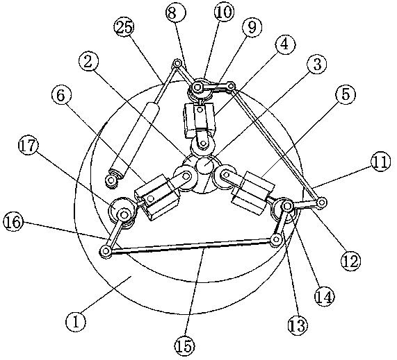
[0022] see Figure 1-2 According to an embodiment of the present invention, a fixing and clamping device for a thermocouple includes a fixing block 1, which can play a supporting role, and a through hole 2 is provided in the middle of the fixing block 1, and the through hole 2 is provided in the middle of the fixing block 1. The hole is a circular through hole. The through hole 2 can facilitate the placement of the thermocouple. The outer wall is tightened and fixed, and the periphery of the through hole 2 is located on the fixed block 1 and is respectively provided with a first mounting block 4, a second mounting block 5 and a third mounting block 6, the first mounting block 4, the second mounting block The block 5 and the third mounting block 6 are fixedly installed on the fixed block 1 at an angle of 120°, and are located around the through hole, which can facilitate the uniform force during extrusion. The first mounting block 4. Both the second mounting block 5 and the th...

Embodiment 2

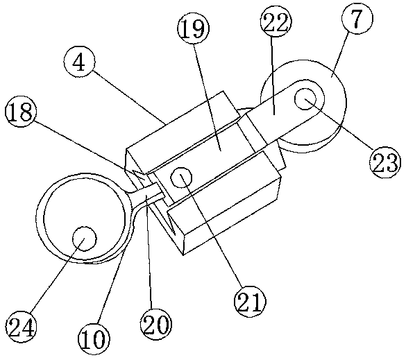
[0025] see figure 2 , for the sliding device, the sliding device includes a chute 18, the chute 18 is a bar-shaped chute 18, and the chute 18 is respectively provided with the first mounting block 4, the second mounting block 5 and the third mounting block. On the mounting block 6, the inside of the chute 18 is provided with a slide block 19, which matches between the chute 18 and the slide block 19, and one end of the slide block 19 is provided with a fixed rod 20, and the fixed rod is convenient for the slide block 19 In connection with the fixed rod 20 , the end of the slider 19 away from the fixed rod 20 is connected to the limit wheel 7 .

Embodiment 3

[0027] see figure 2 , for the fixed rod 20, the fixed rod 20 is respectively fixedly connected with one side of the first turntable 10, the second turntable 14 and the third turntable 17, and the connection between the fixed bar 20 and the slider 19 The movable pins 21 are movably connected to facilitate the movable connection between the fixed rod 20 and the slider 19, and facilitate the movement of the fixed rod 20.


PUM


Abstract

The invention discloses a fixing and clamping device for a thermocouple. The fixing and clamping device comprises a fixing block, wherein a through hole is formed in the middle of the fixing block; the thermocouple is arranged in the middle of the through hole; a first mounting block, a second mounting block and a third mounting block are arranged on the fixing block and around the through hole respectively; sliding devices are arranged on the first mounting block, the second mounting block and the third mounting block; a limiting wheel is arranged on one side of each sliding device; a hydraulic telescopic device is arranged on one side of the fixing block; a first connecting rod is arranged at one end of the hydraulic telescopic device; a second connecting rod is arranged on one side of the first connecting rod; a first rotating disc is arranged on one side of the first connecting rod; a third connecting rod is arranged at one end, far away from the first connecting rod, of the secondconnecting rod; and a fourth connecting rod is arranged at the other end of the third connecting rod. The fixing and clamping device has the advantages of simple structure, convenience in use, convenience in replacement of the thermocouple and high stability.

Description

technical field [0001] The invention relates to the field of thermocouple equipment design, in particular to a fixing and clamping device for thermocouples. Background technique [0002] At present, the clamping and fixing of thermocouples is widely used in the field by pasting the connecting piece. The connecting piece is fixed on the thermocouple by glue, and then the connecting piece is pressed by two flanges and screwed into the screw. Clamp. The disadvantage of this thermocouple fixing method is that it is necessary to purchase additional glue for pasting the thermocouple. Every time the thermocouple is clamped, the connecting piece needs to be glued first, which adds extra operations. After the thermocouple is fixed, due to the adhesive The connecting piece is a soft connection, and the bonding strength of different operators is also different. The thermocouple is easy to slip and move, resulting in the change of the monitored thermocouple point, affecting the accurac...

Claims


Application Information

Patent Timeline
Patent Type & Authority Applications(China)
IPC IPC(8): B25B11/00
CPCB25B11/00
Inventor 段春妮
Owner 西安致开工业自动化工程有限公司
Why Eureka
Try Eureka