Zipper puller tail injection production device for zipper puller

A technology of production equipment and zipper sliders, which is applied in the field of production equipment for pull tabs and tails. It can solve the problems of difficulty in meeting the needs of mass production of glue-injected sliders, low efficiency, and heavy workload, and achieve simple and convenient demoulding and high production efficiency. The effect of improving and improving the demolding efficiency

Pending Publication Date: 2020-02-14
QUANZHOU LICHENG DISTRICT ZHAN AUTOMATION EQUIP
0 Cites 1 Cited by

AI-Extracted Technical Summary

Problems solved by technology

[0004] The present invention provides a pull tab tail production equipment for zipper sliders to solve the existing disadvantages of manual feeding,...

Method used

With reference to Fig. 4 to Fig. 6, each described stretching elastic stop material mechanism 130 comprises material stop plate 131, stage clip 132 and connecting screw rod 133, and above-mentioned zipper slider carrying platform 120 is provided with and zipper slider guide groove 1200 perpendicular Connected material retaining plate chute (because the material retaining plate is installed, not marked in the figure), the material retaining plate 131 can be slidably arranged on the material retaining plate chute, and one end of the material retaining plate 131 protrudes from the The side wall of the zipper puller guide groove 1200, the other end is provided with a connecting portion 1311 extending downwards, and a screw connecting hole 1312 communicating with ...

Abstract

The invention provides a zipper puller tail injection production device for a zipper puller. The zipper puller tail injection production device comprises a rack, an injection molding machine head, a glue injection lower die, an axial moving mechanism, zipper puller feeding devices and a glue injection zipper puller demolding device, wherein the injection molding machine head, the glue injection lower die, the axial moving mechanism, the zipper puller feeding devices and the glue injection zipper puller demolding device are arranged on the rack; the glue injection lower die is arranged below the injection molding machine head; a plurality of core dies are symmetrically arranged on the two sides of the glue injection lower die in the axial direction; the axial moving mechanism is connected with the glue injection lower die so as to drive the glue injection lower die to move in the axis direction. The two zipper puller feeding devices are symmetrically arranged on the two sides of the glue injection lower die in the axial direction correspondingly; and the glue injection zipper puller demolding device is further arranged at the tail end of the glue injection lower die in the axial direction. According to the zipper puller tail injection production device, the zipper puller tail injection procedure of the whole zipper puller is automatically completed mechanically, the production efficiency is greatly improved, the failure rate is low, a lot of manpower and material resources are saved, and the zipper puller tail injection production device is suitable for batch production of glue injection zipper pullers.

Application Domain

Domestic slide fastenersMetal working apparatus

Technology Topic

Batch productionEngineering +4

Image

  • Zipper puller tail injection production device for zipper puller
  • Zipper puller tail injection production device for zipper puller
  • Zipper puller tail injection production device for zipper puller

Examples

  • Experimental program(1)

Example Embodiment

[0042] The technical solutions in the embodiments of the present invention will be clearly and completely described below in conjunction with the accompanying drawings in the embodiments of the present invention. Obviously, the described embodiments are only some, not all, embodiments of the present invention. Based on the embodiments of the present invention, all other embodiments obtained by persons of ordinary skill in the art without making creative efforts fall within the protection scope of the present invention.
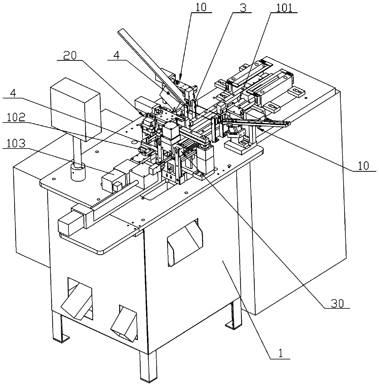
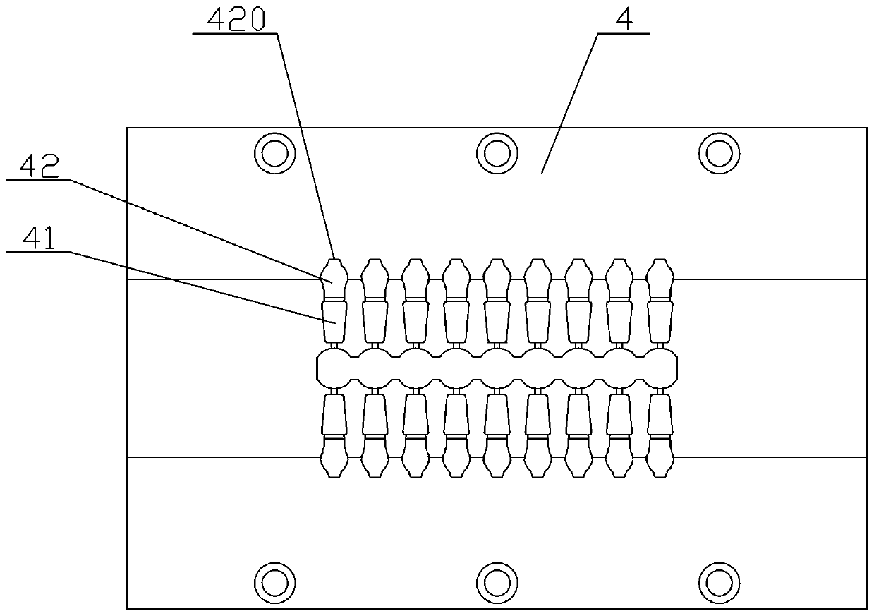
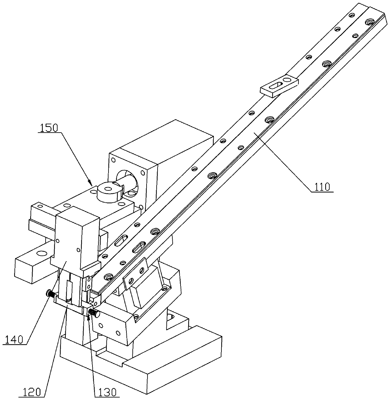
[0043] A kind of pull tab end production equipment for zipper pull, refer to figure 1 , including a frame 1 and an injection molding machine head (not shown in the figure) located on the frame 1, a rubber injection lower mold 4, an axial movement mechanism, a zipper slider feeding device 10 and a rubber injection zipper slider demoulding device 20 , the glue injection upper mold is fixed on the glue injection machine head, and has a symmetrical structure with the glue injection lower mold 4, and the glue injection lower mold 4 is arranged below the injection molding machine head, and the axial movement mechanism includes an axial screw rod 101, a shaft The axial screw slider 102 and the axial screw motor 103, the power output end of the axial screw motor 103 is connected to the axial screw 101, the axial screw slider 102 is set on the axial screw 101, and the glue is injected The mold 2 is fixed on the surface of the top 102 of the axial screw mandrel slider, and moves axially with the axial screw mandrel slider 102 .
[0044] refer to figure 2 , the two axial sides of the glue injection lower mold 4 are symmetrically provided with a plurality of pull-tab glue injection grooves 41, and the outside of each pull-tab glue injection groove 41 is respectively provided with a puller horizontally placed and divided into one end of the chain column. Facing the slider positioning slots 42 on the outside, each slider positioning slot 42 is provided with a notch 420 on the outside of one end of the slider sub-link. A zipper slider feeding device 10 is symmetrically arranged on both sides of the lower die 4 in the axial direction.
[0045] The above-mentioned zipper puller feeding device 10, refer to image 3 and Figure 4 , comprising a zipper puller blanking track 110, a zipper puller carrying platform 120, an elastic stopper mechanism 130, a zipper puller clamping mechanism 140, and a radial push mechanism 150, the zipper puller blanking track 110 is provided obliquely, and the zipper puller carries The platform 120 is connected to the inclined end of the slide slider unloading track 10. A slider guide groove 1200 is provided on the top surface of the slider slider bearing platform 120. Two side walls of the slider guide groove 1200 are respectively symmetrically provided with a top holder. In the elastic stopper mechanism 130 on the side of the front end of the slider, above the slider guide groove 1200 corresponding to the elastic stopper mechanism 130, there is a zipper puller clamping mechanism 140 that clamps the zipper puller from both sides of the upper wing plate of the zipper puller. The pushing mechanism 150 is connected with the zipper slider clamping mechanism 140 to drive the zipper slider clamping mechanism 140 to clamp the zipper slider and move to the corresponding slider positioning groove 42 .
[0046] refer to Figure 4 , the width of the above-mentioned slider guide groove 1200 is slightly greater than the maximum width of the lower flap of the slider slider, and the top surfaces of the two side walls of the slider slider guide groove 1200 are lower than the top surface of the upper flap of the slider slider, so that the slider slider There is sufficient longitudinal height for the upper flap to be clamped by the zipper slider clamping mechanism 140 .
[0047] refer to Figure 4 The above-mentioned radial pushing mechanism 150 includes a radial pushing track 151, a radial pushing slider 152 and a radial pushing cylinder 153, and the radial pushing track 151 is fixed on a support 11 arranged on the side of the slide fastener head blanking track 110 Above, the radial push track 151 is parallel to the central axis of the slider guide groove 1200, the radial push slider 152 is slidably arranged on the radial push track 151, and the radial push cylinder 153 is fixed on the back of the radial push track 151. end, and is connected with the radial push slider 152.
[0048] refer to image 3 or Figure 4 , the above-mentioned zipper slider clamping mechanism 140 is a pneumatic clamping jaw, and the pneumatic clamping jaw is fixedly connected with the radially pushing slider 152 through a connecting plate.
[0049] refer to Figure 4 to Figure 6 Each of the elastic stopper mechanisms 130 includes a stopper plate 131, a clip spring 132 and a connecting screw 133, and the above-mentioned zipper slider carrying platform 120 is provided with a stopper plate chute vertically connected with the zipper slider guide groove 1200 (due to A material retaining plate is installed, not marked in the figure), the material retaining plate 131 can be slidably arranged on the chute of the material retaining plate, and one end of the material retaining plate 131 protrudes from the side wall of the slider guide groove 1200 , the other end is provided with a connecting portion 1311 extending downwards, and a screw connecting hole 1312 communicating with the side wall of the zipper slider bearing platform is opened on the connecting portion 1311, and the connecting screw 133 passes through the screw connecting hole 1312 And screw connected to the side wall of the zipper puller platform 120 , the compression spring 132 is sheathed on the connecting screw 133 outside the screw connecting hole 1312 . One end of the baffle plate 131 protruding from the side wall of the zipper slider guide groove 1200 is provided with an arc-shaped guide part, and the radian of the arc-shaped guide part is adapted to the radian of the side wall of the lower wing of the zipper slider to reduce the zipper pull. The resistance between the zipper head and the baffle when the head is clamped by the clamping mechanism and the zipper head moves.
[0050] The working process of the zipper slider loading device of the present invention is as follows: the zipper slider slides from the zipper slider unloading track 110 to the zipper slider carrier platform 120, the front end of the slider body is blocked by the elastic stop mechanism 130 on both sides, and then the zipper puller The head clamping mechanism 140 is clamped, and finally the radial push mechanism 150 pushes the zipper slider clamping mechanism 140 to overcome the elastic force of the elastic stopper mechanism, and is pushed to the corresponding slider positioning groove 42, and the zipper slider clamping mechanism 140 is loosened. The loading of the zipper head is completed immediately. When the slider is loaded, the slider is positioned in the slider positioning groove 42, and the pull tab is correspondingly dropped into the pull tab glue injection groove 41, and the top surface of the pull tab is closely attached to the top surface of the upper wing of the slider. .
[0051] refer to figure 1 , the two sides of the front end of each of the above-mentioned pulling head feeding devices are respectively provided with detector one 3 and detector two 4, wherein detector one is used to detect in real time whether the zipper head on the lower mold for injection is in place, The second detector is used to detect whether there is a glue-injected zipper head left on the glue-injected lower mold mandrel to be loaded.
[0052] refer to figure 1 , the upper end of the above-mentioned glue injection lower mold 2 is also provided with a glue injection zipper head demoulding device 20, refer to Figure 7 and Figure 8 , the rubber-injected zipper slider demoulding device 20 includes a knife inserting plate 210, a pneumatic gripper 220, a pressing plate mechanism 230, a longitudinal movement mechanism and a radial movement mechanism. Both sides of the injection lower mold 2 are respectively provided with a knife inserting plate 210 in parallel, referring to Figure 9 A plurality of inserting knives 211 adapted to the channel of the glue-injected zipper fastener chain are arranged on the inner side of the inserting knife plate 210 in the axial direction, and the inserting knife 211 is in a U-shaped structure. The side of each knife inserting plate 210 is provided with two described pneumatic jaws 220, and the top surface of inserting knife plate 210 is fixedly connected with a receiving plate 212, and the clamping arm inside each pneumatic jaw 220 passes through described receiving plate 212 and The side walls of the knife inserting plate 210 are fixedly connected to drive all the inserting knives 211 on the knife inserting plate 210 to simultaneously insert or leave the tooth chain channels on both sides of the sub-chain column of the glue-injected zipper head. The pressing plate mechanism 230 includes a pressing plate 231 located on the side of the knife inserting plate 210. The bottom surface of the pressing plate 231 is provided with a plurality of pressing blocks 232 that are correspondingly held on the top surface of the end of the glue-injected zipper away from the split chain post. Each inserting knife The top of 211 is also provided with a top holding block 233 that elastically presses on the top surface of the rubber injection zipper head.
[0053] refer to Figure 7 and Figure 8 The above-mentioned radial movement mechanism is used to drive the knife inserting plate 210 and the pressure plate 231 to move in the radial direction, and the radial movement mechanism includes a radial movement track 241, a radial movement slider 242 and a radial movement drive cylinder 243. The radial moving track 241 is vertically arranged above the knife inserting plate 210, the radial moving slider 242 is co-located on the radial moving track 241, and the radial moving drive cylinder 243 is connected to the radial moving track 241. Move slider 242 to connect.
[0054] refer to Figure 7 and Figure 8 The above-mentioned longitudinal movement mechanism is used to drive the knife inserting plate 210 to move up and down in the longitudinal direction, and the longitudinal movement mechanism includes two longitudinal movement driving cylinders 251, and the two longitudinal movement driving cylinders 251 are arranged below the radial movement track 241 and are connected with The radial movement track 241 is fixedly connected, and the cylinder bodies of the two pneumatic grippers 220 on the side walls of each inserting plate 210 are fixed on the side walls of the radial movement slider 241, and the pressure plate 231 is connected On the cylinder body of the cylinder jaw 220 .
[0055] refer to Figure 10 and Figure 11 The bottom of the above-mentioned pressing plate 231 is provided with a plurality of installation grooves 2330, and a spring 2331 is installed in each installation groove.
[0056] refer to Figure 8 , a connecting seat 221 is fixed on the cylinder body of each pneumatic gripper 220, and each connecting seat 221 is provided with a guide column 222, and the top end of the pressure plate 231 is fixedly connected with two connecting columns 234, each connecting column The top is provided with a vertical screw 235, and each of the connecting columns 234 is correspondingly arranged in the guide column 222, and its vertical screw 235 is correspondingly passed through the upper end of the guide column 222, and passed through the upper end of the guide column 222. A compression spring 236 is sheathed on the vertical screw 235 , and an adjusting nut 237 is provided at the end of the vertical screw 235 . By rotating the adjusting nut 237, the height of the pressing plate 231 can be adjusted to meet the requirements of different thicknesses of zipper sliders.
[0057]The demoulding device of the present invention, its specific working process is as follows: the pneumatic clamping jaw moves, drives the inserting plate on both sides to move inward, makes inserting the inserting knife respectively in the tooth chain channel of one end of the split chain column of the injection zipper head, and at the same time The pressure plate on the pressure plate mechanism is pressed and held on the top surface of the upper wing of the glue-injected zipper head away from the end of the split chain column, and the top holding block is elastically held on the middle front top surface of the upper wing of the glue-injected zipper head (when set When there is a top holding block); then the longitudinal movement mechanism moves to move the pneumatic gripper upwards, and the inserting knife plate, the pressing plate mechanism and the top holding block (when there is a top holding block) act on the glue-injected zipper head at the same time to jointly hold The whole piece of glue-injected zipper head is lifted up synchronously to break away from the glue-injected lower mold; then the radial movement mechanism moves to move the pneumatic grippers, inserting knife plates, etc. to the side collecting place; finally, the pneumatic grippers reset, The entire piece of glue-injected zipper head falls to the material collection place due to loss of support, and the radial movement mechanism and the longitudinal movement mechanism return to their positions in sequence to complete the entire demoulding process.
[0058] refer to figure 1 , the side of above-mentioned glue injection zipper puller demoulding device 20 is also provided with a glue injection zipper puller cutting device 30, with reference to Figure 13 and Figure 14 The rubber injection zipper slider cutting device includes a bracket 310 , a manipulator 320 , a power driving mechanism 330 and a cutting mechanism 340 . Wherein, the bracket 310 is arranged below the end of the above-mentioned radial moving track, and is used to accept the glue-injected zipper pull after demoulding, and the manipulator 20 is clamped on the central glue stick A of the whole piece of glue-injected zipper pull, and the power drive mechanism 30 is connected to the manipulator 320, and is used to pull the manipulator 320 to move along the centerline direction of the center glue stick A of the whole piece of glue-injecting zipper head. B is cut off from center glue stick A. The manipulator 320 sequentially pinches and sends the glue-injected zipper sliders to the cutting mechanism 340 one by one, and the glue tail end of the glue-injected zipper slider is attached to the vertical surface where the cutting line of the cutting mechanism 340 is located.
[0059] refer to Figure 13 and Figure 14 , the manipulator 320 includes a pair of clamping rods 321 and a pneumatic clamping jaw 322 that drives the clamping rods to open or close, and the two clamping arms of the pneumatic clamping jaw 22 are respectively connected to a clamping rod 321 .
[0060] refer to Figure 13 and Figure 14 The above-mentioned power drive mechanism 330 includes a stepping screw motor 331, a screw rod 332 and a screw slider 333, the stepping screw motor 331 is connected to the screw rod 332, and the screw rod 332 is parallel to the center of the whole piece of glue injection zipper head The centerline of the glue stick, the screw mandrel slider 333 is connected to the screw mandrel 332 , and the cylinder body of the above-mentioned pneumatic gripper 322 is fixed on the screw mandrel slider 333 .
[0061] refer to Figure 13 and Figure 15 The above-mentioned cutting mechanism 340 includes an upper cutter 341, a lower cutter 342 and a drive cylinder 343. A lower cutter 341 is respectively fixed in parallel on both sides of the above-mentioned clamping rod 321, and an upper cutter 341 is arranged directly above each lower cutter 341. 342, the drive cylinder 343 is fixed above the upper cutter 342 by a support frame 344, the free end of the drive cylinder 343 is connected to an n-shaped connecting plate 3431, and a guide block 3441 is fixed on the top of the support frame 344, two of the n-type connecting plates 3431 The supporting legs pass through the guide blocks 3441 correspondingly, and the bottom ends thereof are respectively fixedly connected with an upper cutter 341 . The drive cylinder 343 drives the upper cutter 341 to move down and cooperate with the lower cutter 342 to cut off the glue-injected zipper slider from the center glue stick.
[0062] Continue to refer to Figure 13 and Figure 15 , when the upper cutter 341 is in the initial state, that is, when the drive cylinder 343 is not in action, the distance between each upper cutter 341 and its corresponding lower cutter 342 is greater than the connection between the glue tail end of the zipper head B and the central glue stick A C thickness, but less than the thickness of the glue-injected pull-tab. Each upper cutter 341 and the front of the lower cutter 342 are respectively provided with an upper guide piece 345 and a lower guide piece 346. The top surface of 346 and the top surface of upper cutter 341 are in the same horizontal plane. refer to Figure 16 and Figure 17 The gap between the upper guide piece 345 and the lower guide piece 346 forms a front guide groove, while the gap between the upper cutter 341 and the lower cutter 342 forms a rear guide groove. The front ends of the upper guide piece 345 and the lower guide piece 346 are inclined inwardly, and the rear ends are aligned with the upper cutter 341 and the lower cutter 342 respectively. Since the distance between the two upper guide pieces 345 (or the lower guide pieces 346) increases from front to back, and the distance a between the rear ends of the two upper guide pieces 345 or the lower guide pieces 346 is greater than that on both sides of the central glue stick The distance b between the glue tail ends of the two opposite glue-injected zipper heads, and the distance between the glue-injected zipper head glue tail ends on both sides of the center glue stick are the same, therefore, when the glue injection at the front end of the guide piece 345 When the zipper slider moved to the rear end of the upper guide piece 345, the joints between the glue tail ends of the two glue-injected zipper sliders and the central glue stick were elongated to be in a stretched state, and because the upper guide piece 345 and the lower guide piece 346 ends were respectively It is aligned with the upper cutter 341 and the lower cutter 342, so when the glue-injected zipper head moves forward between the upper cutter 341 and the lower cutter 342, the connecting part is still in a stretched state, so that the end of the glue tail is not cut. Raw edges will be left to ensure the cutting quality of the glue-injected zipper pulls.
[0063] refer to Figure 13 , the bottom of the above-mentioned cutting mechanism 340 is provided with a discharge opening 351, and the rear side of the cutting mechanism 340 is also provided with a material blocking plate 352, so as to block and drop the cut glue injection pulling head to the discharge opening 351 middle.
[0064] The glue-injected zipper slider cutting device of the present invention first places the whole piece of glue-injected zipper slider on the bracket after the demoulding, and then the whole piece of glue-injected zipper slider is clamped by the manipulator along the center line of the center glue stick. Direction movement, the connection between the end of the glue tail and the central glue stick of each glue-injected zipper head is transported to the cutting mechanism one by one, and finally the cutting mechanism cuts off from the joint surface between the end of the glue tail and the connection.
[0065] The above is only a specific embodiment of the present invention, but the design concept of the present invention is not limited thereto, and any non-substantial changes made to the present invention by using this concept should be an act of violating the protection scope of the present invention.

PUM

no PUM

Description & Claims & Application Information

We can also present the details of the Description, Claims and Application information to help users get a comprehensive understanding of the technical details of the patent, such as background art, summary of invention, brief description of drawings, description of embodiments, and other original content. On the other hand, users can also determine the specific scope of protection of the technology through the list of claims; as well as understand the changes in the life cycle of the technology with the presentation of the patent timeline. Login to view more.

Similar technology patents

Automatic glue-dispersion chip mounting machine

Owner:常州摩通机器人科技有限公司

Multi-scale greenhouse environment control system based on crop information fusion

InactiveCN102736596ABeneficial to crop physiology and growth needsIncrease productivity
Owner:NANJING AGRICULTURAL UNIVERSITY

Classification and recommendation of technical efficacy words

  • Increase productivity
  • Low failure rate

Preparation method of super-retarding type polycarboxylate superplasticizer

ActiveCN103848944AIncrease productivityUniform product
Owner:KZJ NEW MATERIALS GROUP CO LTD

Refrigeration control system and method for data center

ActiveCN103644632ALow failure rateavoid intervention
Owner:BEIJING BAIDU NETCOM SCI & TECH CO LTD

Electric suspension control device of tractor

ActiveCN103713535AIncreased accuracy and sensitivityLow failure rate
Owner:YANCHENG YANHAI TRACTOR MFG
Why Eureka
Try Eureka