a communication base station

A communication base station and pole technology, applied in the field of communication base stations, can solve problems such as base station antenna drop damage, base station antenna connection break, base station antenna collision, etc., to save manpower and material resources, improve crushing efficiency, and prevent potential safety hazards.

Active Publication Date: 2021-03-23
上海国城科绿色照明科技研究中心有限公司
View PDF11 Cites 2 Cited by
  • Summary
  • Abstract
  • Description
  • Claims
  • Application Information

AI Technical Summary

Problems solved by technology

[0005] In order to make up for the deficiencies in the prior art, the present invention proposes a communication base station. The present invention is mainly used to solve the problem of too many base station antennas installed on the base station tower when the existing communication base stations are installed in some mountainous areas or areas with strong wind. , when the wind in this area is strong, it will cause the base station antennas to collide with each other or the base station antennas will hit the base station tower and the base station antenna connection will be broken, resulting in the phenomenon that the base station antenna will be dropped and damaged, which will not only affect the stable use of the base station antenna, but also cause the base station antenna to be broken. Damage occurs, and there are many birds, it is easy to build bird's nests on the communication base station, it is too dangerous to drive and dismantle artificially, and the installation of sounders cannot be effective for a long time

Method used


Image

  • a communication base station
  • a communication base station
  • a communication base station

Examples


Embodiment Construction

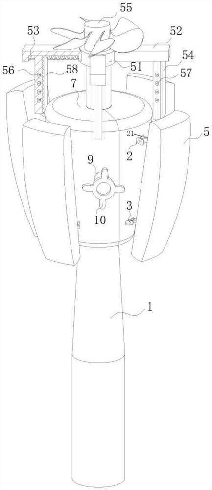
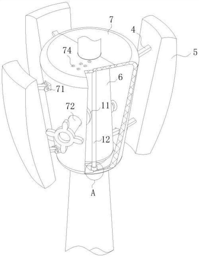
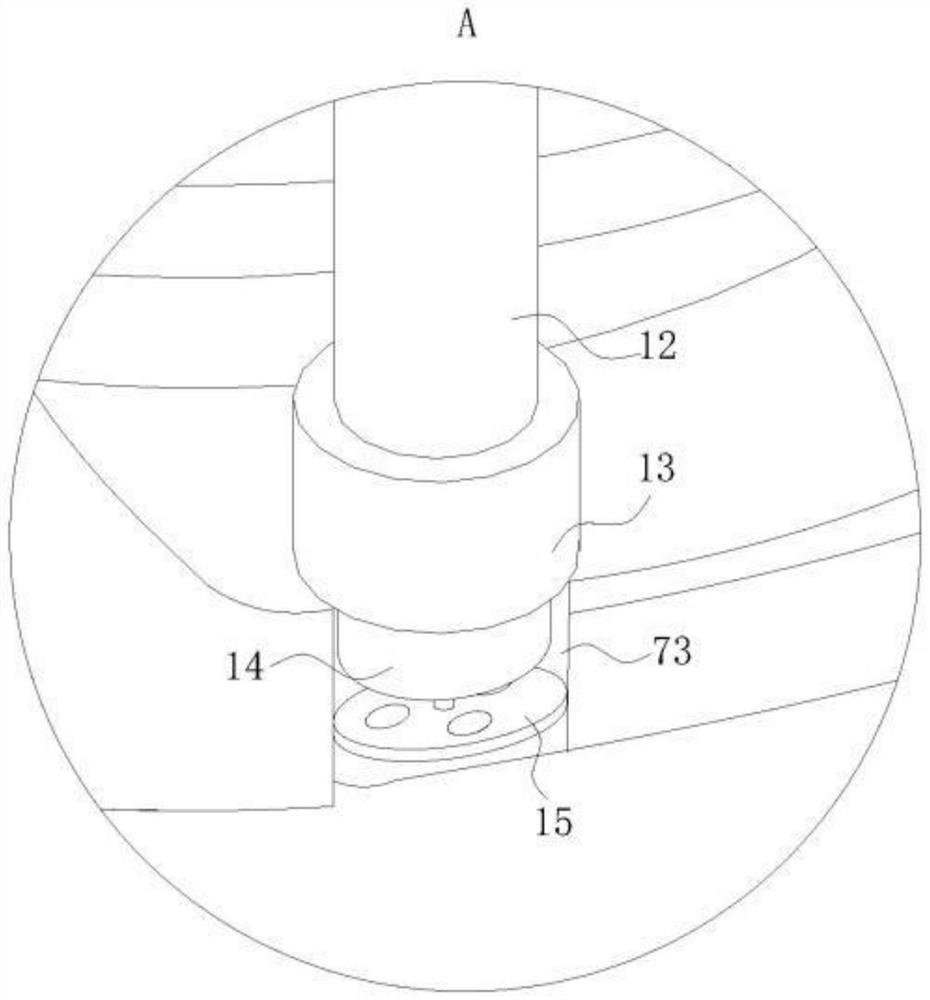
[0023] use Figure 1-Figure 4 A communication base station according to an embodiment of the present invention is described as follows.

[0024] like Figure 1-Figure 4 As shown, a communication base station according to the present invention includes a pole 1; a plurality of support poles 2 are fixed in the circumferential direction of the top of the pole 1, and swing grooves 21 are provided on the plurality of support poles 2; In the swing groove 21, a support column 4 is hinged by a threaded hinge column 3; a base station antenna 5 is installed at the end of the support column 4; the base station antenna 5 is arranged along the circumferential direction of the pole 1 through the support column 4; The rod 1 is sleeved with a rubber ring sleeve 6, and the outside of the rubber ring sleeve 6 is wrapped with a cavity support sleeve 7; the cavity support sleeve 7 is formed by splicing elastic rubber plates; the cavity support sleeve 7 and the rubber ring A plurality of limit s...


PUM


Abstract

The invention belongs to the technical field of communication base stations, and particularly relates to a communication base station. The communication base station comprises an upright rod, a plurality of supporting rods are fixedly arranged at the top of the upright rod in the peripheral direction, and supporting columns are hinged into swing grooves through threaded hinge columns. Base stationantennae are installed at the ends of the supporting columns, the base station antennae are arranged in the peripheral direction of the upright rod through the supporting columns, the upright rod issleeved with a rubber annular sleeve, and the outer portion of the rubber annular sleeve is wrapped with a cavity supporting sleeve. The cavity supporting sleeve is formed by splicing elastic rubber plates; a plurality of limiting springs are uniformly arranged between the cavity supporting sleeve and the rubber annular sleeve. The phenomenon that when the antennae swing in a strong wind environment, the base station antennae are blown by wind power to hit against one another or the base station antennae impact on the upright rod, the base station antennae are damaged due to impact is prevented so that the base station antennae can stably send and receive signals. It is achieved that birds are effectively expelled for a long time, labor is saved, and the service life is prolonged.

Description

technical field [0001] The invention belongs to the technical field of communication base stations, in particular to a communication base station. Background technique [0002] At present, the research and development of 5G technology is very popular all over the world. All mainstream standardization organizations at home and abroad have realized the urgency of the development of 5G technology at this stage, and have formulated relevant 5G research and development plans. From 4G to 5G, user demand continues to increase, indoor and outdoor data services are greatly expanded, and carrier frequency will also be greatly increased. Traditional macro base stations are increasingly unable to cope. In the future 5G era, base stations will inevitably become mainstream on a large scale. [0003] Among the key technologies of 5G is a technology called high-density networking. Its development purpose is to prepare for the large-scale deployment of base stations in the future 5G era. The...

Claims


Application Information

Patent Timeline
Patent Type & Authority Patents(China)
IPC IPC(8): E04H12/00A01M29/16A01M29/32H01Q1/12H04W88/00
CPCA01M29/16A01M29/32E04H12/00H01Q1/1207H01Q1/1242H04W88/00
Inventor 黄友梅周浩张文龙
Owner 上海国城科绿色照明科技研究中心有限公司
Why Eureka
Try Eureka