

Micro substrate integrated waveguide filter with high-order mode rejection
A substrate-integrated waveguide and filter technology, applied in waveguide devices, electrical components, circuits, etc., can solve problems such as unrealizable, wide stopband suppression performance, etc., to achieve improved selectivity, reduced lateral area, and increased crossover coupling effect
- Summary
- Abstract
- Description
- Claims
- Application Information
AI Technical Summary
Problems solved by technology
Method used
Image


Examples
Embodiment 1
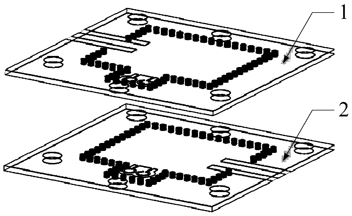
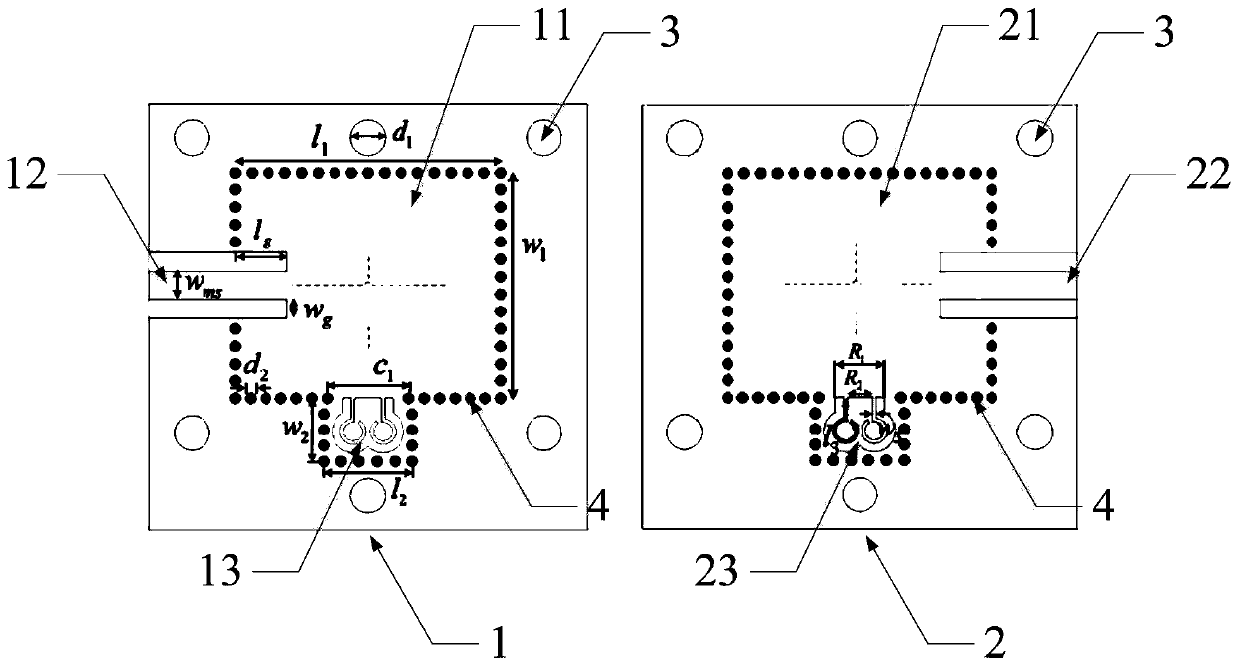
[0062] Embodiments of the present invention provide a miniaturized substrate-integrated waveguide filter with high-order mode suppression, such as figure 1 and figure 2 Commonly shown, including the top PCB board 1 and the bottom PCB board 2, the top PCB board 1 and the bottom PCB board 2 have the same size, and are provided with 6 screw holes 3 with the same diameter at the same position, the top PCB board 1 and the bottom PCB board The boards 2 are closely fitted together by the screws passing through the screw holes 3 .
[0063] The center of the top PCB 1 is provided with a first rectangular SIW resonator 11, the center of the bottom PCB 2 is provided with a second rectangular SIW resonator 21, and one side of the top PCB 1 is provided with a first rectangular SIW resonator The coplanar waveguide input port 12 of the cavity 11, the opposite side of the bottom PCB board 2 is provided with a coplanar waveguide output port 22 extending into the second rectangular SIW resona...
Embodiment 2
[0085] On the basis of the first embodiment, the embodiment of the present invention adds cross-coupling between two rectangular SIW resonators. Such as Figure 4 As shown, the lower surface of the top PCB 1 is etched with a first rectangular groove 14, the first rectangular groove 14 is located in the center of the side of the first rectangular SIW resonator 11 opposite to the first microstrip resonator 13, and the bottom PCB A second rectangular groove 24 is etched on the upper surface of 2, and the second rectangular groove 24 is located in the center of the side of the second rectangular SIW resonator 21 opposite to the second microstrip resonator 23.
[0086] Wherein, the length m of the first rectangular slot 14 and the second rectangular slot 24 1 =2mm; The width n of the first rectangular groove 14 and the second rectangular groove 24 1 =0.2mm; the distance d between the first rectangular groove 14 and the second rectangular groove 24 from the center of the cavity x...
Embodiment 3
[0089] The embodiment of the present invention is based on the first embodiment, near the input and output ports of the filter, on the interface of the rectangular SIW resonant cavity, etch two slender rectangular grooves, and the two slender rectangular grooves are symmetrically distributed to resonate cavity sides. Such as Figure 7 As shown, the lower surface of the top layer PCB 1 is etched with a third rectangular groove 15 and a fourth rectangular groove 16, the third rectangular groove 15 is located near the coplanar waveguide input port 12, the third rectangular groove 15 and the fourth rectangular groove 16 The cavity center of the first rectangular SIW resonant cavity 11 is arranged symmetrically; the upper surface of the bottom PCB board 2 is etched with a fifth rectangular groove 25 and a sixth rectangular groove 26, and the sixth rectangular groove 26 is located near the output port 22 of the coplanar waveguide , the fifth rectangular groove 25 and the sixth rect...
PUM
| Property | Measurement | Unit |
|---|---|---|
| Thickness | aaaaa | aaaaa |
| Length | aaaaa | aaaaa |
| Length | aaaaa | aaaaa |
Abstract
Description
Claims
Application Information