Automatic marking machine

An automatic, laser marking technology, used in welding equipment, laser welding equipment, metal processing equipment, etc., can solve the problems of inconvenient operation, waste of cost, small size of chip products, etc.

Pending Publication Date: 2020-02-18
SHENZHEN TETE SEMICON EQUIP CO LTD
View PDF0 Cites 5 Cited by
  • Summary
  • Abstract
  • Description
  • Claims
  • Application Information

AI Technical Summary

Problems solved by technology

Due to the small size of the chip product, it is inconvenient to operate, so most of the chips manufactured by the manufacturer are card-type production, and a single card is evenly covered with multiple chip prod

Method used


Image

  • Automatic marking machine
  • Automatic marking machine
  • Automatic marking machine

Examples


Embodiment Construction

[0036] The following will clearly and completely describe the technical solutions in the embodiments of the present invention with reference to the accompanying drawings in the embodiments of the present invention. Obviously, the described embodiments are only part of the embodiments of the present invention, not all of them. Based on the embodiments of the present invention, all other embodiments obtained by persons of ordinary skill in the art without creative efforts fall within the protection scope of the present invention.

[0037] It should be noted that if there is a directional indication (such as up, down, left, right, front, back...) in the embodiment of the present invention, the directional indication is only used to explain the position in a certain posture (as shown in the accompanying drawing). If the specific posture changes, the directional indication will also change accordingly.

[0038] In addition, if there are descriptions involving "first", "second" and ...


PUM


Abstract

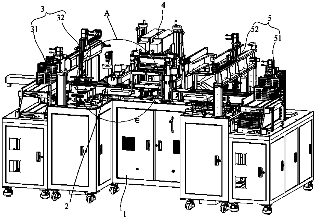
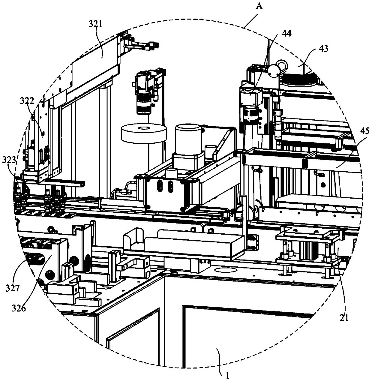
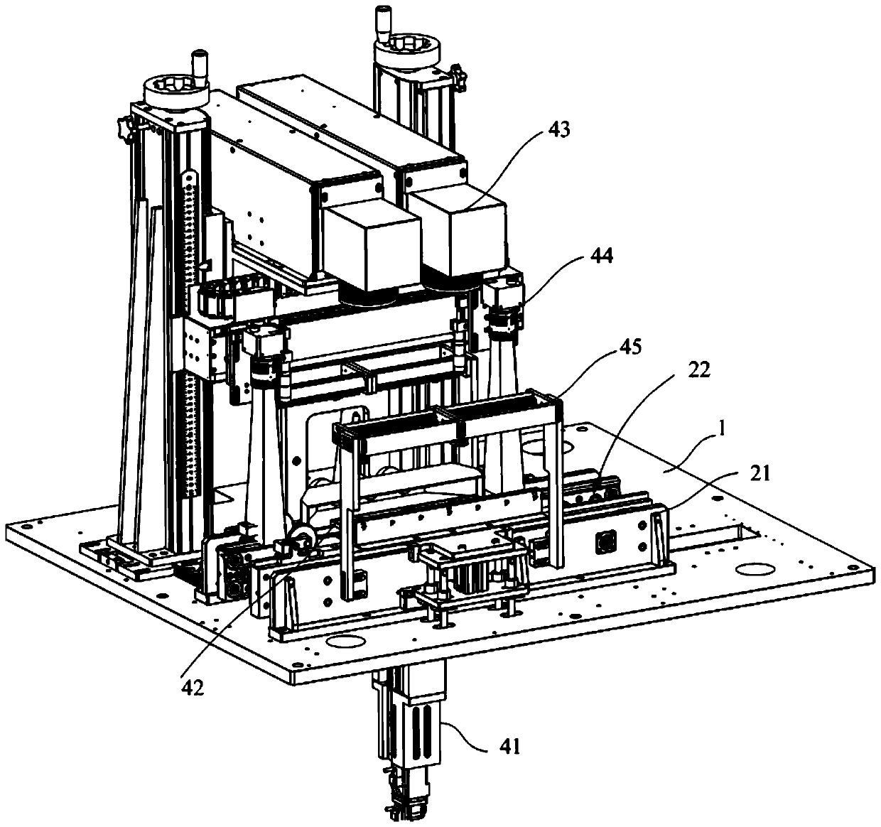
The invention discloses an automatic marking machine. The automatic marking machine comprises a machine base, a material conveying mechanism, a feeding mechanism and a laser marking mechanism; the material conveying mechanism is arranged on the machine base, and the material conveying mechanism comprises a material conveying belt; the feeding mechanism is arranged on the machine base, the feedingmechanism comprises a first feeding assembly and a second feeding assembly, the first feeding assembly is correspondingly arranged at one end of the material conveying belt, the first feeding assemblyis used for pushing a card type chip to the material conveying belt, the second feeding assembly is arranged adjacent to the material conveying belt, the second feeding assembly comprises a mechanical claw, and the mechanical claw is used for clamping the card type chip on the second feeding assembly to the material conveying belt; and the laser marking mechanism is arranged on the machine base and is arranged right opposite to the material conveying belt, and the laser marking mechanism is used for marking the card type chip. According to the automatic marking machine, automatic marking of the chip can be realized, and the production efficiency of the chip is improved.

Description

technical field [0001] The invention relates to the technical field of chip manufacturing equipment, in particular to an automatic marking machine. Background technique [0002] In the chip manufacturing industry, the application of laser marking is more and more extensive. Due to the small size of the chip product, it is inconvenient to operate, so most of the chips manufactured by the manufacturer are card-type production, and a single card is evenly covered with multiple chip products, and there are many inconveniences in the whole process of manual operation. In this way, the speed is slow, and many people need to coordinate operations for many times, the labor cost is high, and the cost is wasted. [0003] The above content is only used to assist in understanding the technical solution of the present application, and does not mean that the above content is admitted as prior art. Contents of the invention [0004] The main purpose of the present invention is to propo...

Claims


Application Information

Patent Timeline
IPC IPC(8): B23K26/362B23K26/70
CPCB23K26/362B23K26/702
Inventor 周建阳吴星王庆丰蔡俊杨星星
Owner SHENZHEN TETE SEMICON EQUIP CO LTD
Why Eureka
Try Eureka