Pull disc

A technology of trays and pull rods, which is applied in the direction of hand-held tools and manufacturing tools, can solve the problems of unreliable connection between the claw and the bearing, inconsistent pulling force of the claw, and easily damaged bearings. Effect

Pending Publication Date: 2020-02-18
南通高盛机械制造有限公司 +1
View PDF0 Cites 0 Cited by
  • Summary
  • Abstract
  • Description
  • Claims
  • Application Information

AI Technical Summary

Problems solved by technology

There are defects such as unreliable connection between the claw and the bearing, which is easy to slip; the claw is easy to break; the pulling force of the claw is inconsistent, and the bearing is easy to be damaged.

Method used


Image

  • Pull disc
  • Pull disc

Examples


Embodiment Construction

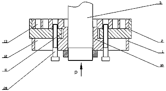
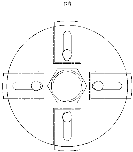
[0008] Such as figure 1 and figure 2 As shown, the technical solution adopted in this specific embodiment is: a pull plate, consisting of a tray 1 and a slider 2, the center of the tray 1 is provided with a through hole 10 connected to one end of the pull rod 3; the middle of the side of the tray 1 A plurality of chutes 11 extending horizontally to the center of the tray 1 are arranged at intervals along the circumference; a plurality of guide grooves 12 connected with the chutes 11 are arranged on the bottom of the tray 1; , and the positioning hole 13 corresponding to the guide groove 12, the slider 2 is set in the chute 11 of the tray 1, one end of the slider 2 is provided with a positioning pin 20, and one end of the positioning pin 20 can be inserted into the positioning hole on the tray 1 13, the other end of the positioning pin 20 stretches out of the guide groove 12 below the tray 1.

[0009] When assembling or disassembling the bearing, according to the diameter of...


PUM


Abstract

The invention provides a pull disc. The pull disc comprises a tray and a sliding block. The center of the tray is provided with a through hole connected with one end of a pull rod. The middle of the side face of the tray is provided with a plurality of sliding slots extending horizontally to the center of the tray at intervals along the circumference. A plurality of guide slots communicating withthe sliding slots correspondingly is formed in the lower surface the tray. A plurality of positioning holes communicating with the sliding slots correspondingly and corresponding to the guide slots are formed in the upper surface of the tray. The sliding block is arranged in the sliding slots on the tray. One end of the sliding block is provided with a positioning pin. One end of the positioning pin can be inserted into the positioning holes in the upper surface of the tray, and the other end of the positioning pin extends out of the guide slots in the lower surface of the tray. The pull dischas the remarkable advantages that the structure is firm and not likely to be broken, the size of the diameter is adjustable, a bearing is pulled overall, the connection is reliable and the bearing isnot likely to be broken.

Description

technical field [0001] The invention relates to a puller, in particular to a puller with adjustable diameter. Background technique [0002] Existing tools for mounting and dismounting bearings all adopt claws to connect bearings for drawing. There are defects such as unreliable connection between the claw and the bearing, which is easy to slip; the claw is easy to break; the pulling force of the claw is inconsistent, and the bearing is easy to be damaged. Contents of the invention [0003] Aiming at the defects and deficiencies of the prior art, the present invention provides a pull plate for bearing assembly and disassembly, which is composed of a tray and a slider. The center of the tray is provided with a through hole connected with one end of the pull rod; There are a number of chutes extending horizontally to the center of the tray at intervals on the circumference; there are a number of guide grooves corresponding to the chute on the bottom of the tray; Positioning...

Claims


Application Information

Patent Timeline
Patent Type & Authority Applications(China)
IPC IPC(8): B25B27/06
CPCB25B27/06
Inventor 耿晓曦马超陈文慧陈进海
Owner 南通高盛机械制造有限公司
Why Eureka
Try Eureka