
Anti-falling protection device for wheeled robot

The technology of a wheeled robot and protection device, which is applied in the field of intelligent robots, can solve problems such as falls and robot damage

Pending Publication Date: 2020-02-18
向宇辰
View PDF5 Cites 10 Cited by
  • Summary
  • Abstract
  • Description
  • Claims
  • Application Information

AI Technical Summary

Problems solved by technology

[0004] The purpose of the present invention is to solve the disadvantages of the wheeled robot existing in the prior art that, when encountering bumpy roads, it often falls due to being unable to maintain balance, which will undoubtedly cause damage to the robot. Anti-fall protection device for wheeled robots

Method used


Image

  • Anti-falling protection device for wheeled robot
  • Anti-falling protection device for wheeled robot
  • Anti-falling protection device for wheeled robot

Examples


Embodiment 1

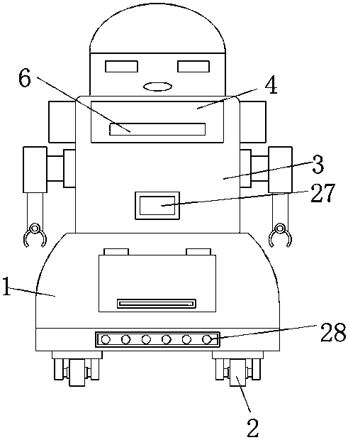
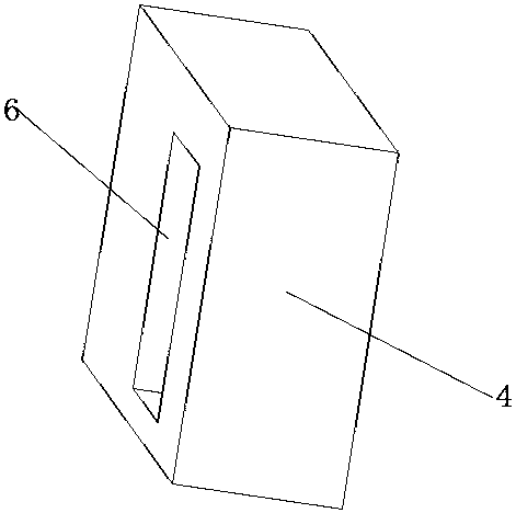
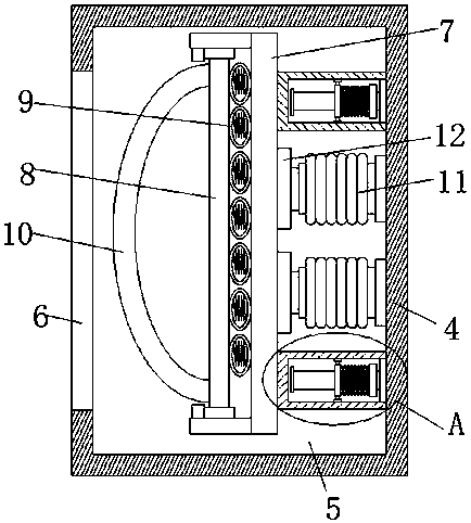
[0025] refer to Figure 1-7 , a wheeled robot anti-fall protection device, including a base 1, a robot body 3 is fixedly installed on the top of the base 1, and a protective seat 4 is arranged around the robot body 3, and an installation cavity 5 is opened on the protection seat 4, and the installation cavity 5 An ejection groove 6 is provided on the inner wall of one side of the installation cavity 5, two electromagnets 11 symmetrically arranged are fixedly installed on the inner wall of one side of the installation cavity 5, a push plate 7 is arranged in the installation cavity 5, and a push plate 7 is fixedly installed on one side of the installation cavity 5. Two limit seats 13 are symmetrically arranged, and a sliding plate 14 is fixedly installed in the limit seat 13, and a sliding rod 15 is slidably connected to the sliding plate 14, and one end of the sliding rod 15 is fixedly connected to the inner wall of one side of the installation cavity 5, The outer side of the s...

Embodiment 2

[0027]Further improvement on the basis of Embodiment 1: universal wheels 2 are fixedly installed on the four corners of the bottom of the base 1, and the universal wheels 2 are used to facilitate the movement of the robot body 3 to any position; the sliding plate 14 is fixedly installed with straight lines Bearing, the sliding rod 15 runs through the inner ring of the linear bearing and is slidably connected with the inner ring of the linear bearing. The frictional force of the lateral movement of the sliding rod 15 can be reduced by using the linear bearing; The same elastic spring is fixedly installed on the inner wall, and the elasticity of the elastic airbag 9 can be improved by using the elastic spring; a maintenance hole is provided on the side inner wall of the adjustment chamber 17, and a maintenance door is sealed and hinged in the maintenance hole, and the maintenance door can be used to facilitate Carry out maintenance to the components in the adjustment cavity 17; t...


PUM


Abstract

The invention belongs to the technical field of intelligent robots, and particularly relates to an anti-falling protection device for a wheeled robot. The following scheme is provided for solving theproblems that in the using process of an existing wheeled robot, when the existing wheeled robot encounters a bumpy road surface, the existing wheeled robot often falls due to the fact that the existing wheeled robot cannot keep balance, and the robot is undoubtedly damaged. The anti-falling protection device for the wheeled robot comprises a base, a robot body is fixedly mounted at the top of thebase, protective seats are arranged on the periphery of the robot body, mounting cavities are formed in the protective seats, and pop-up grooves are formed in the inner walls of one sides of the mounting cavities. When the robot body encounters an abnormal route, on one hand, the situation that the robot body falls when passing through the abnormal road section can be reduced by adjusting the gravity center of the base, and on the other hand, arc-shaped anti-collision plates can be popped up from the pop-up grooves, so that the situation that the robot body falls when passing through the abnormal route, and consequently the exterior of the robot body is damaged is prevented.

Description

technical field [0001] The invention relates to the technical field of intelligent robots, in particular to an anti-fall protection device for a wheeled robot. Background technique [0002] The reason why an intelligent robot is called an intelligent robot is because it has a well-developed "brain". What works in the brain is the central processing unit, a computer that has a direct connection to the person who operates it. Most importantly, such a computer can perform purposeful actions. It is for this reason that we say that such robots are real robots, even though they may differ in appearance. [0003] When the current wheeled robot is in use, when it encounters a bumpy road, it often falls due to being unable to maintain balance, which will undoubtedly cause damage to the robot. Therefore, we have proposed a wheeled robot anti-fall protection device to solve the problem. the questions raised above. Contents of the invention [0004] The purpose of the present inve...

Claims


Application Information

Patent Timeline
Patent Type & Authority Applications(China)
IPC IPC(8): B25J5/00B25J19/00B25J9/16
CPCB25J5/007B25J19/00B25J9/1674B25J9/1694B25J9/16
Inventor 向宇辰杨洋王晓健符颖翀黄治镡刘小东
Owner 向宇辰
Learn More