Hand brake device

A handbrake and handle technology, applied in the field of electric vehicles, can solve the problems of handbrake device brake failure, movable clamps cannot be effectively inserted into the gear teeth, etc., to achieve the effect of avoiding handbrake failure, reliable braking, and not easy to damage

Inactive Publication Date: 2020-02-18
姚亨明
View PDF0 Cites 0 Cited by
  • Summary
  • Abstract
  • Description
  • Claims
  • Application Information

AI Technical Summary

Problems solved by technology

[0002] When the vehicle stops or starts, the hand brake will be used. The inventor of the present invention has found that due to reasons such as improper operation or structural design, after the existing hand brake device has been used for a long time, the mounting piece 1 and the mounting piece 2 are located in the mounting holes. Both left arc parts will produce valgus deformation to both sides. When the deformation is sufficient, the movable clamping plate will not be able to effectively engage with the gear teeth, which will cause the braking failure of the handbrake device.

Method used


Image

  • Hand brake device
  • Hand brake device
  • Hand brake device

Examples


Embodiment Construction

[0022] The present invention will be further described below in conjunction with accompanying drawing and specific implementation.

[0023] A handbrake device, comprising:

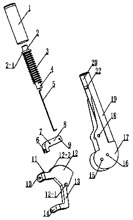
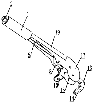
[0024] Such as figure 1 As shown: the installation sleeve, the upper end of the installation sleeve is provided with an installation cylinder 19, and one side of the installation cylinder 19 is provided with a strip-shaped opening 20, and the installation cylinder 19 is located on the strip-shaped opening One side of 20 is symmetrically provided with a mounting piece 17 and a mounting piece 2; the mounting piece 17 and the mounting piece 2 are provided with a through mounting hole 16 and a mounting hole 2 18;

[0025] Sector-shaped chuck 12, described sector-shaped chuck 12 is located between described mounting piece one 17 and mounting piece two, and is connected with mounting piece one 17 and mounting piece two rotationally; Sector-shaped chuck 12 is provided with shaft 12 -1, through the shaft 12-1 an...


PUM


Abstract

The invention discloses a hand brake device. The hand brake device comprises a mounting sleeve, a fan-shaped chuck, a limiting column, a limiting plate, a handle, a pressing rod, a connecting rod, a spring and a movable clamping plate. The hand brake device has the following beneficial effects that by arranging the movable clamping plate with the inverted U-shaped clamping groove, the arc-shaped parts located on the left side of a mounting hole II in a mounting piece I and a mounting piece II in the using process can be prevented from turning outwards, so that the problem of hand brake failureduring braking is avoided; and compared with the prior art, the device has the advantages of being more reliable in braking and not prone to being damaged.

Description

technical field [0001] The invention belongs to the field of electric vehicles, in particular to a hand brake device. Background technique [0002] When the vehicle stops or starts, the hand brake will be used. The inventor of the present invention has found that due to reasons such as improper operation or structural design, after the existing hand brake device has been used for a long time, the mounting piece 1 and the mounting piece 2 are located in the mounting holes. Both left side arc parts will produce valgus deformation to both sides. When the amount of deformation is sufficient, the movable clamping plate will not be able to be effectively locked into the gear teeth, which will cause the braking failure of the handbrake device. Contents of the invention [0003] The purpose of the present invention is to provide a handbrake device to solve the problems raised in the above-mentioned background technology. [0004] To achieve the above object, the present invention...

Claims


Application Information

Patent Timeline
IPC IPC(8): B60T7/10
CPCB60T7/10
Inventor 姚亨明
Owner 姚亨明
Why Eureka
Try Eureka