Batching hopper for die steel production

A technology of die steel and hopper, applied in the direction of charge, charge composition/state, charging processing type, etc., can solve the problem of inconvenient discharging and other problems, and achieve the effect of simple operation and labor saving.

Inactive Publication Date: 2020-02-18
湖北三冶重工集团有限公司
View PDF0 Cites 0 Cited by
  • Summary
  • Abstract
  • Description
  • Claims
  • Application Information

AI Technical Summary

Problems solved by technology

[0003] The purpose of the present invention is to solve the disadvantages of inconvenient material dumping in the prior art, and propose a batching hopper for mold steel production

Method used


Image

  • Batching hopper for die steel production
  • Batching hopper for die steel production

Examples


Embodiment 1

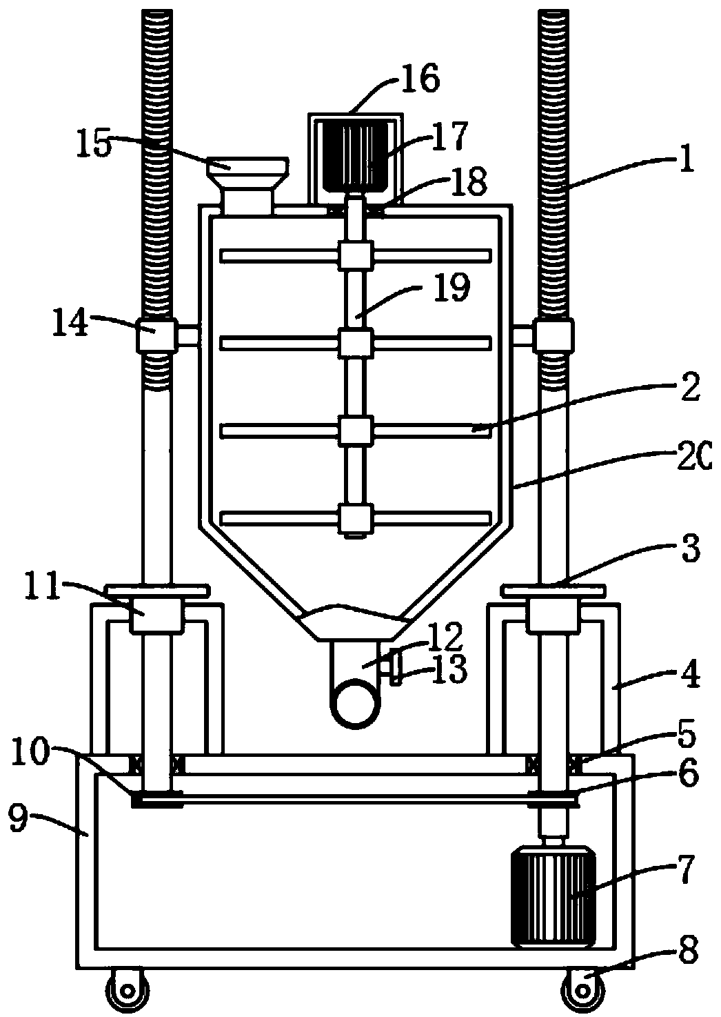
[0016] refer to Figure 1-2 , a batching hopper for the production of die steel, comprising a box body 9, the lower end of the box body 9 is fixedly connected with a roller 8, and both sides of the upper end of the box body 9 are fixedly connected with first bearings 5, and the inner parts of the two first bearings 5 The shaft surfaces are fixedly connected with a rotating shaft 1, the lower ends of the two rotating shafts 1 are connected by a transmission mechanism, the upper end of the rotating shaft 1 is provided with an external thread, the external thread is threaded with a threaded sleeve 14, and a housing 20 is fixedly connected between the two threaded sleeves 14 , the upper end of the housing 20 is connected to a feed port 15, and the lower end of the housing 20 is connected to a discharge pipe 12. The discharge pipe 12 is provided with a valve 13, and the first motor 7 moves forward to drive the rotating shaft 1. Rotate, so that the threaded sleeve 14 rises, drives t...

Embodiment 2

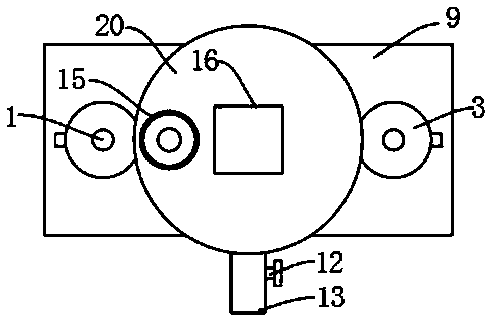
[0020] refer to figure 2 , as another preferred embodiment of the present invention, the difference from Embodiment 1 is that the transmission mechanism includes a rotating wheel 6 fixedly connected to the lower end of the rotating shaft 1, and a belt 10 is sleeved between the two rotating wheels 6, through which the belt 10 to the effect of transmission so as to drive the two rotating wheels 6 to rotate simultaneously.

Embodiment 3

[0022] refer to Figure 1-2 , as another preferred embodiment of the present invention, the difference from Embodiment 1 is that the lower ends of the two rotating shafts 1 are provided with connecting sleeves 11, and the opposite outer sides of the two connecting sleeves 11 are fixedly connected with L-shaped support rods 4, The lower end of the L-shaped support rod 4 is fixedly connected with the box body 9, and the rotating shaft 1 is fixedly connected with a support plate 3, and the support plate 3 abuts against the upper end of the connection sleeve 11, and the support plate 3 is supported by the connection sleeve 11, thereby The rotating shaft 1 plays a supporting role, which is beneficial to reduce the pressure of the gravity of the raw material on the first bearing 5 , thereby prolonging the service life of the first bearing 5 .


PUM


Abstract

The invention relates to the technical field of dies, in particular to a batching hopper for die steel production. The batching hopper comprises a box body, and first bearings are fixedly connected totwo sides of the upper end of the box body correspondingly; the inner shaft surfaces of the two first bearings are fixedly connected with rotating shafts, and the lower ends of the two rotating shafts are connected through a transmission mechanism; the upper ends of the rotating shafts are provided with external threads, the external threads are in threaded connection with threaded sleeves, and ashell is fixedly connected between the two threaded sleeves; one side of the upper end of the shell communicates with a feeding port, the lower end of the shell communicates with a discharging pipe,and the discharging pipe is provided with a valve; and the shell is internally provided with a stirring mechanism, one side of the box body is fixedly connected with a first motor, and an output shaftof the first motor is fixedly connected with the rotating shafts. The batching hopper has the characteristics of facilitating feeding of ingredients.

Description

technical field [0001] The invention relates to the technical field of molds, in particular to a batching hopper used for the production of mold steel. Background technique [0002] When producing modular steel, it is necessary to use a batching device to mix the raw materials, and then pour the batching into the melting furnace for melting production. After the batching of the existing batching hopper is completed, the melting furnace has a certain height, and the batching hoppers are all placed on the ground. When pouring the raw materials, it is necessary to use a forklift or other tools, and the operation is complicated. Contents of the invention [0003] The purpose of the present invention is to solve the disadvantage of being inconvenient to pour materials in the prior art, and propose a batching hopper for mold steel production. [0004] In order to achieve the above object, the present invention adopts the following technical solutions: [0005] Design a batchin...

Claims


Application Information

Patent Timeline
Patent Type & Authority Applications(China)
IPC IPC(8): F27B14/08F27D3/00
CPCF27B14/0806F27D3/0025F27D2003/0065F27D2003/0083F27M2001/02F27M2003/13
Inventor 叶兴发
Owner 湖北三冶重工集团有限公司
Why Eureka
Try Eureka