
Graphite hole detection device

A detection device, graphite technology, applied in the direction of mechanical diameter measurement, mechanical depth measurement, etc., can solve the problems of inconvenient access, inaccurate measurement, time-consuming accuracy, etc., to meet the requirements of reducing the time limit of personnel skills and experience, and reducing the difficulty of operation coefficient, the effect of improving work efficiency

Pending Publication Date: 2020-02-18
QINGDAO JINNUO AUTOMOBILE MOLD CO LTD
View PDF1 Cites 0 Cited by
  • Summary
  • Abstract
  • Description
  • Claims
  • Application Information

AI Technical Summary

Problems solved by technology

The disadvantage of this test method is that it is inconvenient to take, because the length of the graphite column is only less than 0.5mm longer than the depth of the graphite hole, and the gap between the graphite column and the graphite hole in the diameter direction is only about 0.1mm; the second is to measure Inaccurate, due only to the experience of the measurer
However, the difference between the graphite hole diameter and the graphite column diameter cannot exceed the allowable value, otherwise it will affect the self-lubricating performance; the third is that the measurement efficiency is low and time-consuming
[0003] The Chinese patent document whose patent announcement number is CN205403638U discloses a kind of dial indicator that can detect the depth of small holes. People use instruments to obtain more accurate results, but manpower is needed to observe the dial indicator, which still has low efficiency, Time-consuming and inaccurate problems

Method used


Image

  • Graphite hole detection device
  • Graphite hole detection device
  • Graphite hole detection device

Examples


Embodiment Construction

[0025] The following will clearly and completely describe the technical solutions in the embodiments of the present invention with reference to the accompanying drawings in the embodiments of the present invention. Obviously, the described embodiments are only some, not all, embodiments of the present invention.

[0026] In the description of the present invention, it should be noted that the orientation or positional relationship indicated by the terms "inner", "outer", "upper", "lower", "front", "rear" etc. are based on the Orientation or positional relationship is only for the convenience of describing the present invention and simplifying the description, and does not indicate or imply that the referred device or element must have a specific orientation, be constructed and operated in a specific orientation, and thus should not be construed as a limitation of the present invention.

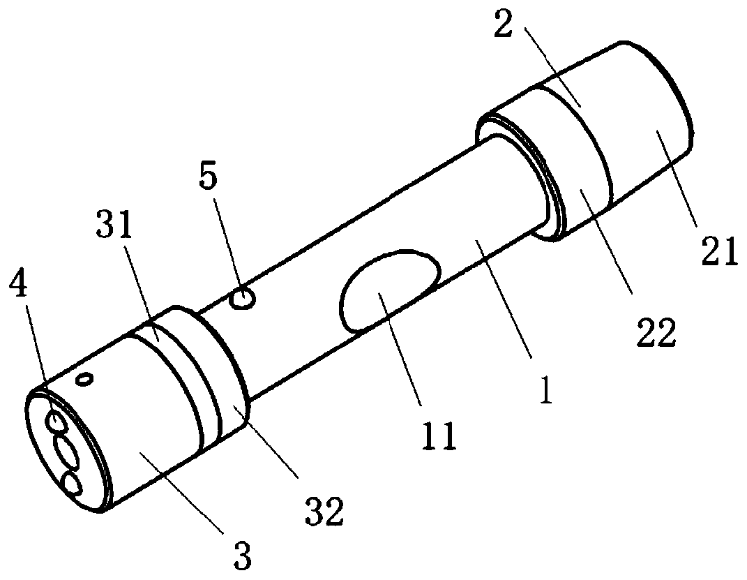
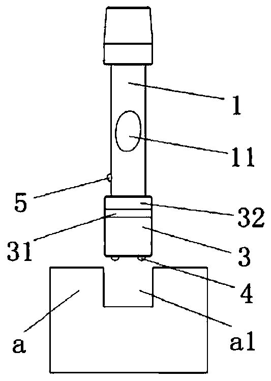
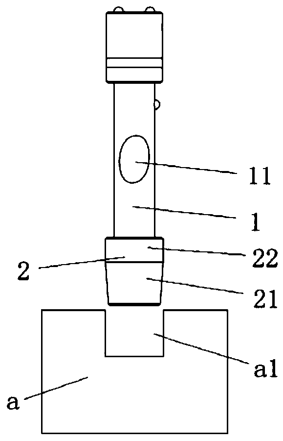
[0027] like Figure 1-3 As shown, the present embodiment provides a graphite hole detectio...


PUM


Abstract

The invention relates to a graphite hole detection device, in particular to a detection device for a graphite hole in a graphite self-lubricating wear-resisting plate. The graphite hole detection device comprises a handheld part; an indicating part is arranged at the side wall of the handheld part; a depth testing part is arranged at one end of the handheld part; and a diameter testing part is arranged at the other end of the handheld part. A contact sensor, a qualified section and a depth upper part are sequentially arranged at one side, away from the handheld part, of the depth testing end.And an indicating part is in signal connection with the contact sensor. The detection device has the following beneficial effects: whether the graphite hole is qualified or not can be quickly, conveniently and accurately measured; the working efficiency is improved; the operation difficulty coefficient of a post is reduced; and the requirements of the post on personnel skills and experience time limit are reduced, so that the personnel can quickly work on regular posts.

Description

technical field [0001] The invention relates to a graphite hole detection device, in particular to a detection device for graphite holes drilled on a graphite self-lubricating wear-resistant plate. Background technique [0002] At present, the detection method of the graphite hole of the graphite self-lubricating wear-resistant plate is: the operator manually puts the graphite column into the graphite hole, and compares the matching of the diameter and length of the graphite column with the depth of the graphite hole by using the experienced sense of touch and eye view. Condition. The disadvantage of this test method is that it is inconvenient to take, because the length of the graphite column is only less than 0.5mm longer than the depth of the graphite hole, and the gap between the graphite column and the graphite hole in the diameter direction is only about 0.1mm; the second is to measure Inaccurate, due to the experience of the surveyor only. However, the difference be...

Claims


Application Information

Patent Timeline
Patent Type & Authority Applications(China)
IPC IPC(8): G01B5/18G01B5/12
CPCG01B5/12G01B5/18
Inventor 邰燕
Owner QINGDAO JINNUO AUTOMOBILE MOLD CO LTD
Learn More