
Test fixtures for contactors

A technology for testing devices and contactors, which is applied in measuring devices, testing of machine/structural components, testing of mechanical components, etc., and can solve problems such as overtravel, burning, and welding of contacts

Active Publication Date: 2022-03-08
SCHNEIDER ELECTRIC IND SAS
View PDF12 Cites 0 Cited by
  • Summary
  • Abstract
  • Description
  • Claims
  • Application Information

AI Technical Summary

Problems solved by technology

For example, the overtravel of the main contact is insufficient due to excessive ablation. If it is not found in time, it is very likely to cause the contact to melt and weld, and in severe cases, the system will be damaged.
At present, the contactor can only be replaced passively when there is contact melting or lack of phase failure during use, which poses a great hidden danger to the safety of electrical lines and the personal safety of users
The existing contactor detection method is manual detection, and the detection equipment is an electric meter, which can only simply detect the on-off state of the contactor, and cannot accurately detect the contact ablation; if large-scale special equipment is used, the contactor needs to be removed. It takes a long time, labor costs are expensive, work efficiency is low, and labor intensity is high
[0003] One of the mechanical properties of the contactor is reflected in the overtravel of the contact. With the increase of the number of uses, the overtravel of the contact decreases continuously, and the pressure of the contact decreases accordingly. In severe cases, it will cause welding and burning of the contact , causing damage to equipment or even paralysis of electrical lines

Method used


Image

  • Test fixtures for contactors
  • Test fixtures for contactors
  • Test fixtures for contactors

Examples


Embodiment Construction

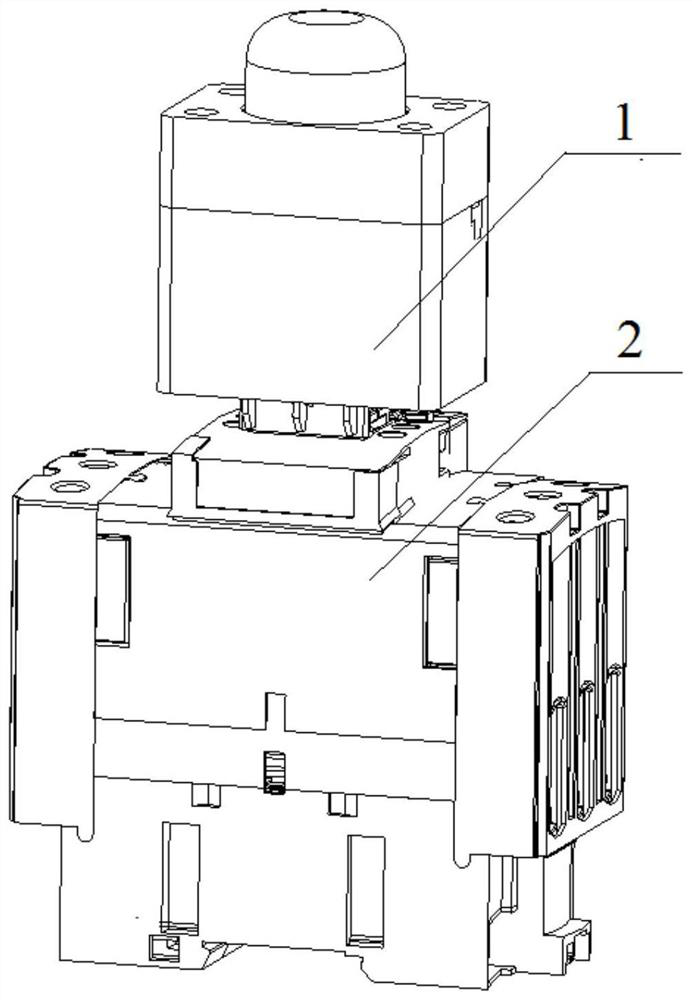
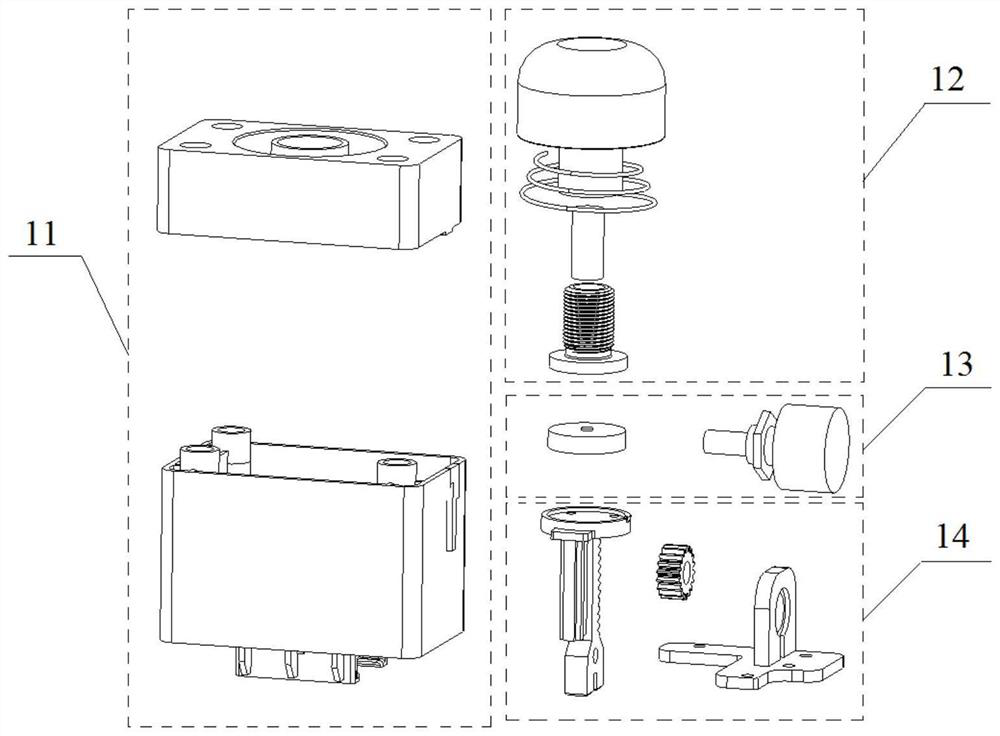
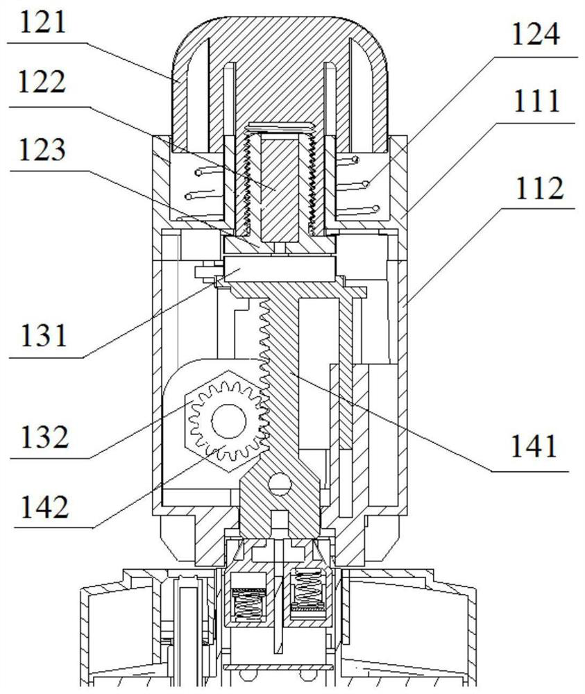
[0025] Various embodiments according to the present invention will be described in detail with reference to the accompanying drawings. Here, it is to be noted that, in the drawings, the same reference numerals are assigned to components having substantially the same or similar structures and functions, and repeated descriptions about them will be omitted. If not specifically stated, the term "sequentially including A, B, C, etc." only indicates the arrangement order of the included components A, B, C, etc., and does not exclude the inclusion of components between A and B and / or between B and C. Possibility of other components. .

[0026] The accompanying drawings in this specification are schematic diagrams, which assist in explaining the concept of the present invention, and schematically represent the shapes of various parts and their interrelationships.

[0027] Below, refer to Figure 1 to Figure 11 , to describe in detail preferred embodiments according to the present ...


PUM


Abstract

The invention relates to a testing device for a contactor, comprising: a housing; an actuation module, mounted on the housing, and moving under the action of an external force; a transmission module, connected with the actuation module and a moving contact assembly of the contactor, and The movement of the actuating module is transmitted to the moving contact assembly; the sensor module is installed to the transmission module, and the displacement of the moving contact assembly and the reaction force of the moving contact assembly spring received by the moving contact assembly are measured through the transmission module. During the operation of the device, the actuating module moves under the action of external force, causing the transmission module to move, and then the moving contact assembly moves. When the moving contact assembly moves to a predetermined position, it stops moving, and then releases the external force. At this time, the moving contact The component will move under the action of the spring of the moving contact component. The reaction force of the spring of the moving contact component and the displacement of the moving contact component will be output through the transmission module through the sensor module. Through the displacement and reaction force of the moving contact component The size relationship determines the overtravel of the contactor.

Description

technical field [0001] The invention relates to a testing device for a contactor. Background technique [0002] The contactor is an electrical control component with large production volume and wide application range, which can be used to frequently switch AC and DC main circuits and large-capacity control circuits. Cooperating with relays can realize functions such as timing operation, interlock control, quantitative control, pressure application and undervoltage protection. The mechanical performance of the contactor (mainly refers to the contact overtravel) will directly affect its electrical life. For example, the overtravel of the main contact is insufficient due to excessive ablation. If it is not found in time, it is very likely to cause contact welding, and in severe cases, it will cause system damage. At present, the contactor can only be replaced passively when the contacts are welded or lack of phase failure during use, which poses a great hidden danger to the s...

Claims


Application Information

Patent Timeline
Patent Type & Authority Patents(China)
IPC IPC(8): G01M13/00
CPCG01M13/00
Inventor 田海峰宋来根M.阿巴迪
Owner SCHNEIDER ELECTRIC IND SAS
Learn More