Yarn guiding device for textile

A wire guide device and wire guide technology, applied in the textile field, can solve problems such as inflexible use and inconvenient scheduling

Active Publication Date: 2020-10-23
苏州康博纺织科技有限公司
View PDF16 Cites 1 Cited by
  • Summary
  • Abstract
  • Description
  • Claims
  • Application Information

AI Technical Summary

Problems solved by technology

[0002] With the continuous development of my country's textile industry, the requirements for textile technology are getting higher and higher. The original meaning of textile is taken from the general term of spinning and weaving. However, with the continuous development and improvement of the textile knowledge system and discipline system, especially non-woven fabrics After the emergence of technologies such as woven textile materials and three-dimensional composite weaving, the current textile is not only traditional hand spinning and weaving, but also non-woven technology, modern three-dimensiona

Method used


Image

  • Yarn guiding device for textile
  • Yarn guiding device for textile
  • Yarn guiding device for textile

Examples


Embodiment 1

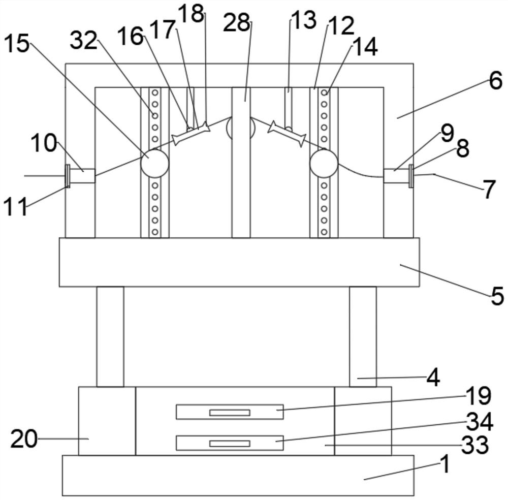
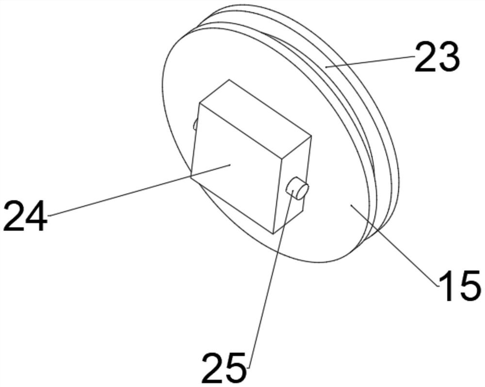
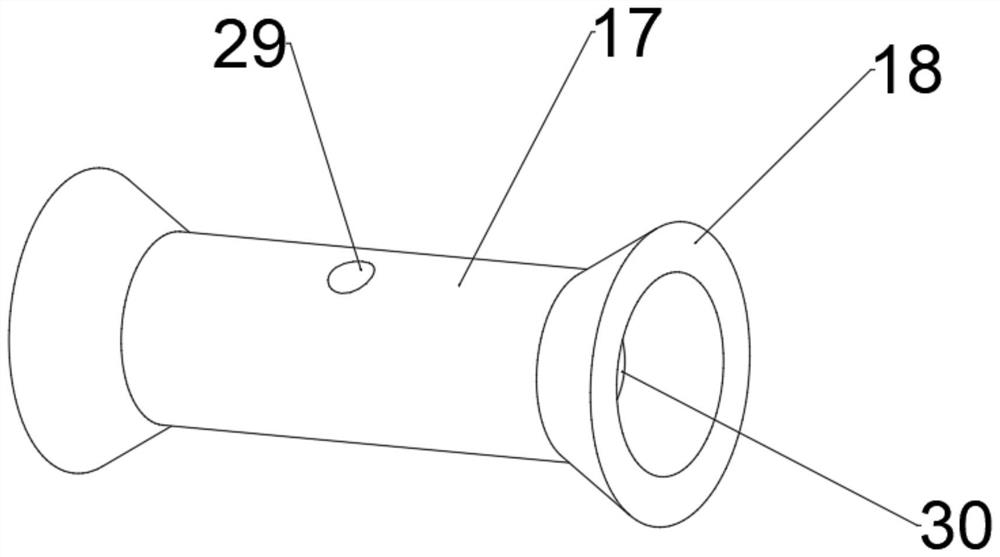
[0035] refer to Figure 1 to Figure 5, a kind of guide wire device for weaving, comprising a support plate 5 and a guide box 6, the top of the support plate 5 is connected with a guide box 6 by bolts, the upper surface of the support plate 5 and the inner top surface of the guide box 6 are provided with a second The third chute 22 and the second chute 21, the second chute 21 and the third chute 22 are slidably connected with the second slider 31 inside, and the end of the second slider 31 away from the bottom of the third chute 22 is bolted. There is a first slide plate 12, the second slide block 31 is bolted to the second slide plate 28 at one end away from the bottom of the second slide slot 21, and the front side of the first slide plate 12 and the rear side of the second slide plate 28 are provided with first slide slots 14. The first slider 24 is slidably connected in the first chute 14, and the end of the first slider 24 away from the first chute 14 is bolt-connected wit...

Embodiment 2

[0044] refer to Figure 4 , a guide wire device for textiles. Compared with Embodiment 1, this embodiment is provided with a running mechanism under the base 1, the running mechanism includes a rolling wheel 2 and a brake plate 3, and the bottom of the base 1 is connected with a rolling wheel 2 by bolts. , the bolts on the scroll wheel 2 are connected with a brake plate 3, and the device can move freely by using the scroll wheel 2. When the device moves to a designated position, the brake plate 3 is used to stop the scroll wheel 2 from rotating and limit the rotation of the scroll wheel 2. Make the device stable at the designated place, ensure that it will not move when the device is running, and increase its practicability.

[0045] Working principle: Use the scroll wheel 2 to make the device move freely. When the device moves to the specified position, use the brake plate 3 to stop the scroll wheel 2 from rotating, and limit the rotation of the scroll wheel 2, so that the de...


PUM


Abstract

The invention discloses a yarn guiding device for textile. The yarn guiding device comprises a supporting plate and a yarn guiding box, wherein the yarn guiding box is arranged on the upper portion ofthe supporting plate; third sliding grooves and second sliding grooves are formed in the upper surface of the supporting plate and the top face of the interior of the yarn guiding box, and second sliding blocks are arranged inside the second sliding grooves and the third sliding grooves; and first sliding plates are arranged at the ends, away from the bottoms of the third sliding grooves, of thesecond sliding blocks, and second sliding plates are arranged at the ends, away from the bottoms of the second sliding grooves, of the second sliding blocks. According to the yarn guiding device for textile, spun yarns are guided in yarn guiding grooves, when the positions of yarn guiding wheels need to be changed for different spun yarns, the first sliding plates and the second sliding plates aremoved, due to the fact that the horizontal positions of the first sliding plates and the second sliding plates are different, the yarn guiding wheels on the first sliding plates face the outside, theyarn guiding wheels on the second sliding plates face the inside, therefore the yarn guiding grooves in the yarn guiding wheels are located on the same straight line, and the situation that spun yarns fall off from the yarn guiding wheels due to the fact that the angle of the yarn guiding wheels is incorrect in the running process of the device is avoided.

Description

technical field [0001] The invention relates to the technical field of textiles, in particular to a textile guiding device. Background technique [0002] With the continuous development of my country's textile industry, the requirements for textile technology are getting higher and higher. The original meaning of textile is taken from the general term of spinning and weaving. However, with the continuous development and improvement of the textile knowledge system and discipline system, especially non-woven fabrics After the emergence of technologies such as woven textile materials and three-dimensional composite weaving, the current textile is not only traditional hand spinning and weaving, but also non-woven technology, modern three-dimensional weaving technology, modern electrostatic nano-netting technology, etc. , industrial and decorative textiles. Modern textile refers to a multi-scale structure processing technology of fibers or fiber aggregates. Textile mainly includes ...

Claims


Application Information

Patent Timeline
IPC IPC(8): B65H57/14B65H57/12B65H57/04B65H57/06
CPCB65H57/14B65H57/12B65H57/04B65H57/06B65H2701/31
Inventor 陈明
Owner 苏州康博纺织科技有限公司
Why Eureka
Try Eureka