Thrombus interceptor
An interceptor and thrombus technology, applied in the field of thrombus interceptor, to achieve the effect of a wide range of application scenarios
- Summary
- Abstract
- Description
- Claims
- Application Information
AI Technical Summary
Problems solved by technology
Method used
Image
Examples
Embodiment 1
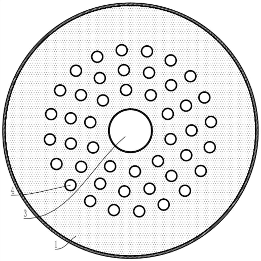
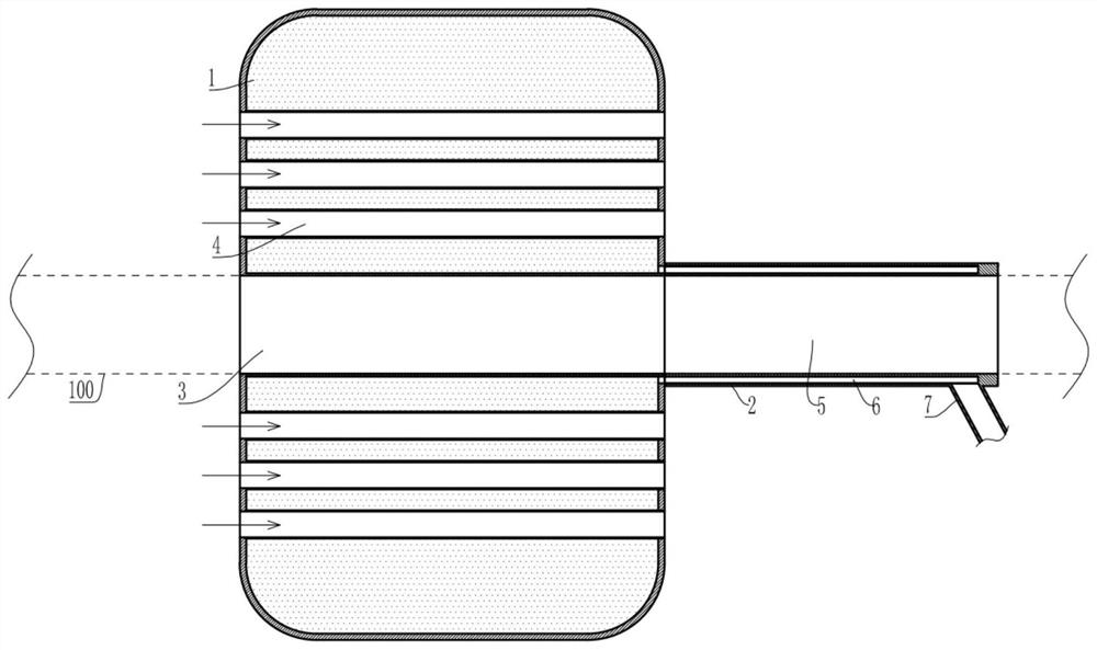
[0039] Embodiment 1 is basically as attached figure 1 and figure 2 Shown: a thrombus interceptor, including a support bag 1 and a communication tube 2 fixedly connected to the right side of the support bag 1, the support bag 1 is integrally formed with a placement hole 3 and a plurality of flow holes 4, and the cross-section of the support bag 1 The outer contour is circular, the placement hole 3 is located in the center of the support bag 1, and the circulation hole 4 is in the circumferential direction of the placement hole 3; the diameter of the circulation hole 4 is smaller than the minimum cross-section of the thrombus, the circulation hole 4 is used for blood to flow through, and the placement hole 3 is used for To accommodate the catheter 100 or the guide wire, the support bag 1 can abut against the inner wall of the blood vessel after being inflated; the connecting pipe is communicated with the support bag 1, and the connecting pipe can be connected to an external mac...
Embodiment 2
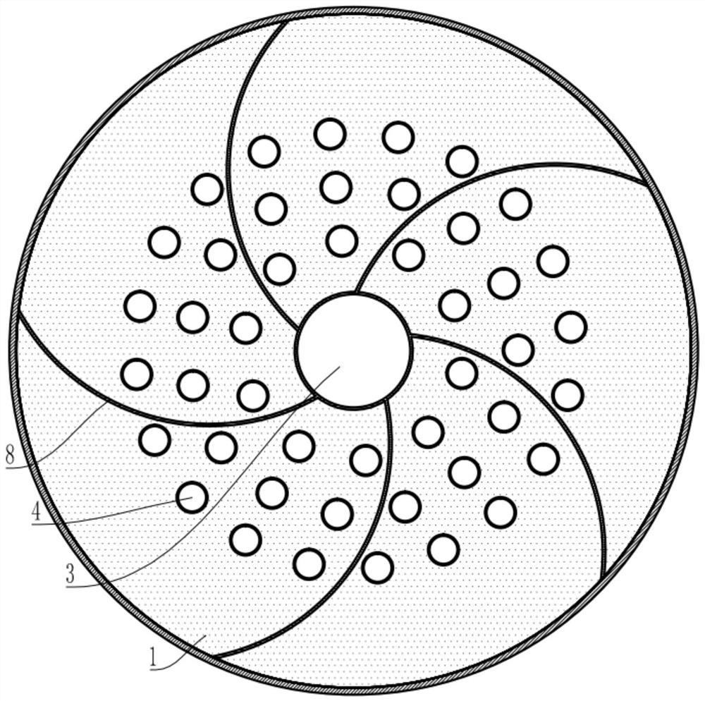
[0047] The second embodiment is basically as attached Figure 3 to Figure 5 As shown, the second embodiment makes the following improvements on the basis of the first embodiment: the support bag 1 is formed with a connecting rib 8, the connecting rib 8 is in a spiral shape, and the connecting rib 8 gradually extends from the center of the support bag 1 to the outer wall of the support bag 1 ; combine image 3 and Figure 4 , when the number of connecting ribs 8 is multiple, this embodiment takes five as an example, and the multiple connecting ribs 8 are evenly distributed along the circumferential direction of the center of the support bag 1 . combine Figure 5 , when the number of connecting ribs 8 is one, the spiral connecting ribs 8 extend from the center of the support bag 1 to the outer wall of the support bag 1 in a spiral manner; crease.
[0048] The specific implementation process is as follows: when the present embodiment is adopted, the setting of the helical con...
Embodiment 3
[0050] The third embodiment is basically as attached Image 6 As shown, the third embodiment makes the following improvements on the basis of the second embodiment: the end face of the support bag 1 away from the connecting pipe is a convex curved surface or a conical surface. Image 6 Take the convex surface as an example.
[0051] When using this embodiment, the support bag 1 is away from one end of the connecting pipe (that is, the attached Image 6 The left end of the support bag 1) extends into the blood vessel first, and the end face is an outer curved surface or a tapered surface, which is conducive to reducing the friction during the insertion of the support bag 1 into the blood vessel (or insertion into the target tube); in addition, the outer curved surface or the tapered surface of the support bag 1 The intercepted thrombus acts as a diversion, and the intercepted thrombus will move to the edge of the support bag 1 close to the blood vessel wall, reducing the speed...
PUM
 Abstract
Description
Claims
Application Information
 - R&D
- Intellectual Property
- Life Sciences
- Materials
- Tech Scout
- Unparalleled Data Quality
- Higher Quality Content
- 60% Fewer Hallucinations
Browse by: Latest US Patents, China's latest patents, Technical Efficacy Thesaurus, Application Domain, Technology Topic, Popular Technical Reports.
© 2025 PatSnap. All rights reserved.Legal|Privacy policy|Modern Slavery Act Transparency Statement|Sitemap|About US| Contact US: help@patsnap.com


