Dispensing machine

A dispensing machine and dispensing technology, applied in the field of dispensing machines, can solve the problems of inconvenient loading and unloading, low compatibility, improper operation, etc., and achieve the effect of saving handling time

Pending Publication Date: 2020-01-10
SELF ELECTRONICS CO LTD
View PDF1 Cites 2 Cited by
  • Summary
  • Abstract
  • Description
  • Claims
  • Application Information

AI Technical Summary

Problems solved by technology

[0004] 1. The dispensing manipulator can only move up and down and move horizontally and vertically in the plane. It cannot realize the deflection of the dispensing manipulator, and the dispensing of some corners is not in place;
[0005] 2. Due to the long size of the strip lamp, loading and unloading is very inconvenient and the efficiency is low, and improper operation can easily deform the strip lamp housing;
[0006] 3. The lamp fixture with fixed size is still used, which cannot be adjusted according to the size of the lamp, and the versatility is low

Method used


Image

  • Dispensing machine
  • Dispensing machine
  • Dispensing machine

Examples


Embodiment Construction

[0046] The present invention will be further described in detail below in conjunction with the accompanying drawings and embodiments.

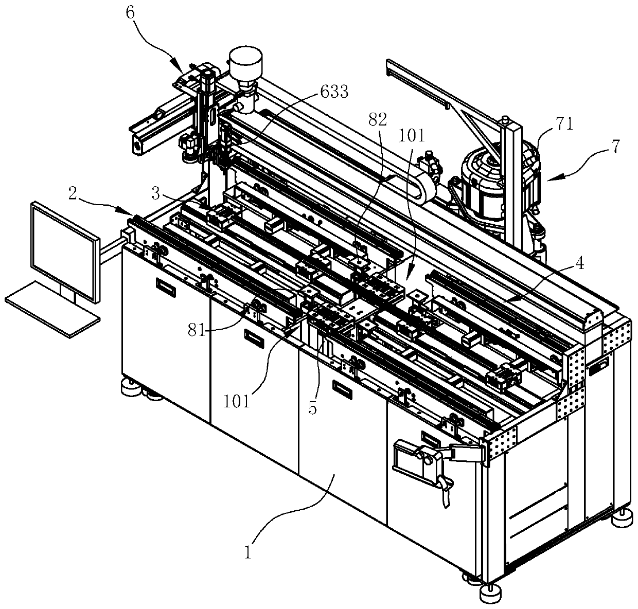
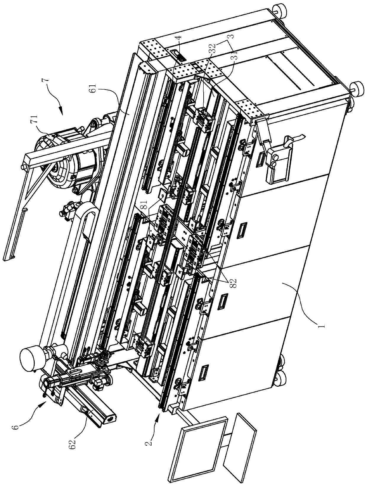
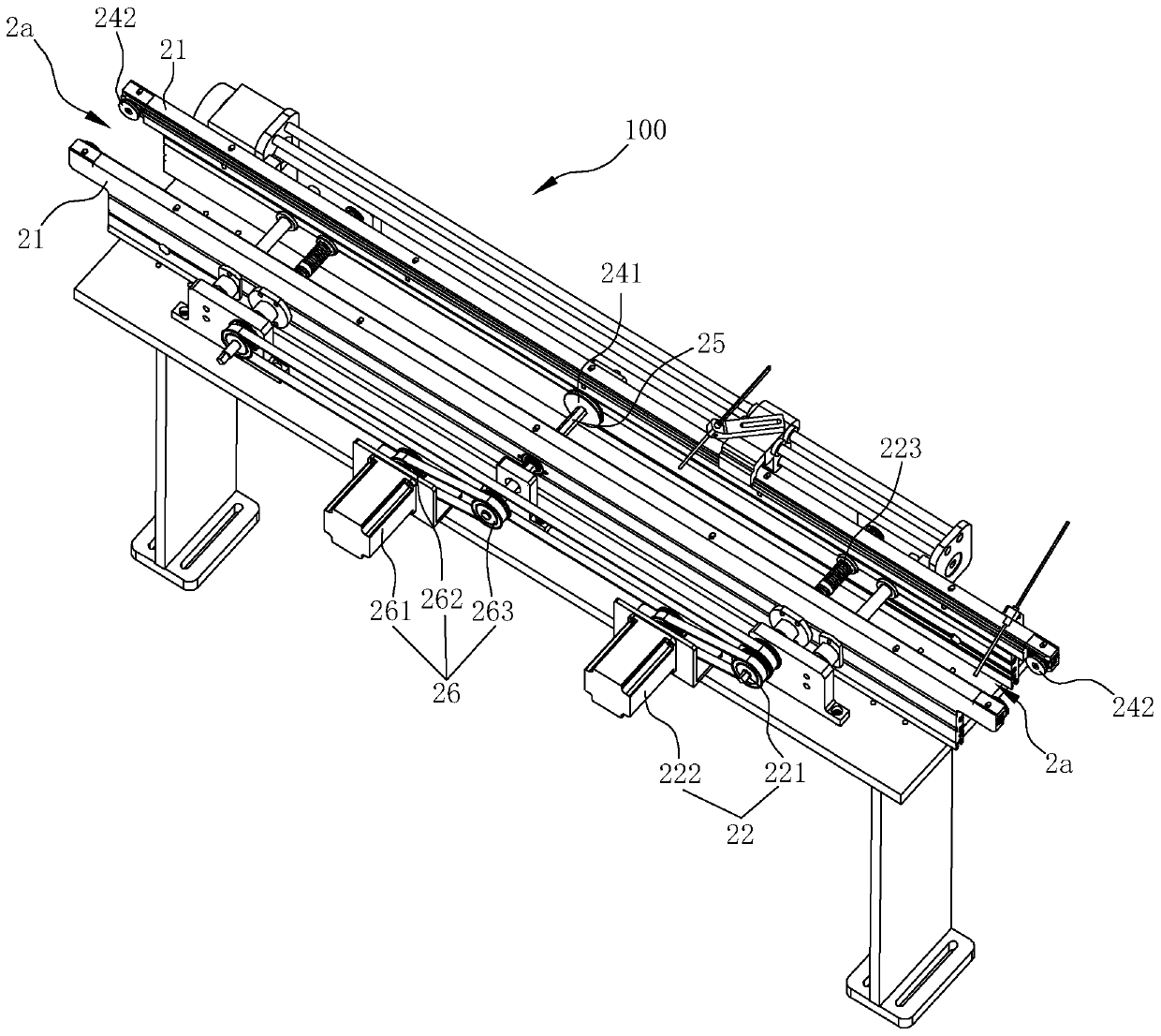
[0047] Such as Figure 1-9 As shown, it is a preferred embodiment of the present invention. In this embodiment, the dispensing machine includes a fuselage 1, a feeding mechanism 2, a positioning and clamping mechanism 3, a dispensing terminal 6, a feeding mechanism 4 and a moving The feeding mechanism 5, wherein the feeding mechanism 2 is arranged laterally on one side of the fuselage 1, the positioning clamping mechanism 3 is arranged on the fuselage 1 and is located downstream of the feeding mechanism 2, and the unloading mechanism 4 is located on the side of the positioning clamping mechanism 3 Downstream and laterally arranged on the other side opposite to the loading mechanism 2, the material shifting mechanism 5 is arranged in the middle of the fuselage 1 and can move back and forth between the loading mechanism 2 and the unloading mecha...


PUM


Abstract

The invention relates to a dispensing machine which is provided with a feeding mechanism, a material moving mechanism, a positioning and clamping mechanism and a discharging mechanism in sequence fromthe upstream of a machine body to the downstream of the machine body. The feeding mechanism and the discharging mechanism both extend transversely and are correspondingly arranged on the two sides ofthe machine body, and a dispensing valve of a dispensing end head can move freely relative to the machine body; the material moving mechanism is arranged at the middle portion of the machine body andcan move back and forth between the feeding mechanism and the discharging mechanism in the longitudinal direction; the feeding mechanism can transport a lamp housing before dispensing to the machinebody, and the discharging mechanism can transport the lamp housing after dispensing to leave the machine body and transfer the lamp housing to the next process; the time of manual handling is saved; the material moving mechanism can move between the feeding mechanism and the discharging mechanism back and forth, a transfer platform can ensure that the lamp housing is lifted from the middle of theentire lamp housing, and therefore deformation of the lamp housing during movement is avoided; and in addition, a chuck in the positioning and clamping mechanism is arranged so that fixation of the lamp housing transferred to the positioning and clamping mechanism can be ensured, and it is ensured that the lamp housing does not move in the dispensing process.

Description

technical field [0001] The invention relates to the field of dispensing glue for lamps, in particular to a glue dispensing machine. Background technique [0002] LED strip lamps mainly include strip lamp aluminum base, strip lamp lens, lampshade, LED lamp board and installation end cover. In the assembly process of LED strip lamps, a special glue dispensing process is required to fix some parts. The existing strip lamps need to be manually dispensed with the help of specific fixtures. The way of manual fixation with fixtures is often It is the workers who rely on experience to operate the positioning, not only the pass rate is worrying, but also the production efficiency is relatively low, and the manual dispensing will cause the dispensing process to be inconsistent with the next process. At the same time, different types of fixtures will take up a lot of storage space, which is very inconvenient. [0003] For this reason, the Chinese utility model patent whose patent numb...

Claims


Application Information

Patent Timeline
Patent Type & Authority Applications(China)
IPC IPC(8): B05C5/02B05C13/02
CPCB05C5/02B05C13/02
Inventor 陈江平李勋万晓云刘良福卢祖栋
Owner SELF ELECTRONICS CO LTD
Why Eureka
Try Eureka