
Defect detection method for road deceleration strip

A detection method and technology of speed bumps, which are applied in image data processing, instruments, computing, etc., can solve the problems of affecting traffic safety, large amount of calculation and storage space, harm to vehicles and personnel, etc., so as to avoid waste of resources and improve computing speed. , the effect of high defect detection rate

Active Publication Date: 2020-02-18
CHANGAN UNIV
View PDF22 Cites 8 Cited by
  • Summary
  • Abstract
  • Description
  • Claims
  • Application Information

AI Technical Summary

Problems solved by technology

The working conditions of the speed bump are relatively harsh, and are often damaged due to vibration, shock, sun exposure and aging. This will expose the nails when the speed bump is installed, causing potential harm to vehicles and personnel, which has seriously affected traffic safety. installation
[0003] At present, the existing technical solutions for the speed bumps with black blocks and yellow blocks alternately use machine learning methods, based on convolutional neural networks, to judge whether there are speed bumps in the road and whether they are defective speed bumps by training positive and negative sample sets However, the amount of calculation and storage space in the calculation process is huge, so that the real-time detection of road speed bump defects cannot be normally applied in engineering, so it is necessary to improve the detection of this speed bump

Method used


Image

  • Defect detection method for road deceleration strip
  • Defect detection method for road deceleration strip
  • Defect detection method for road deceleration strip

Examples


Embodiment Construction

[0046] The present invention will be further described in detail below in conjunction with specific embodiments, which are explanations of the present invention rather than limitations.

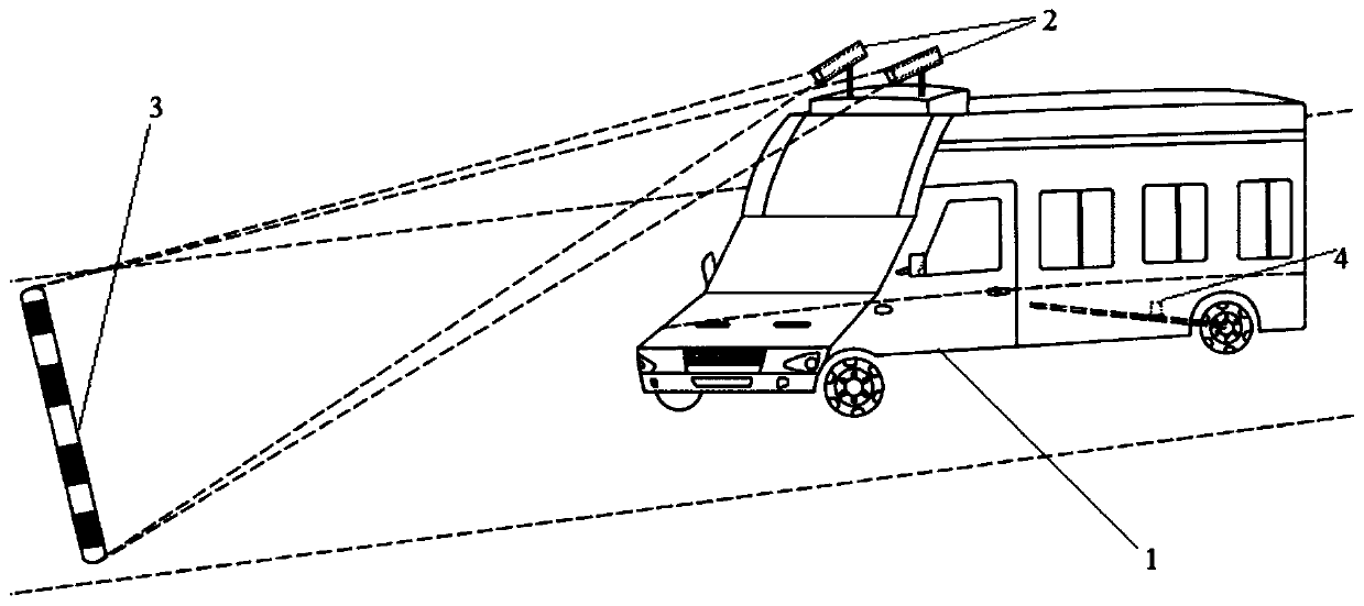
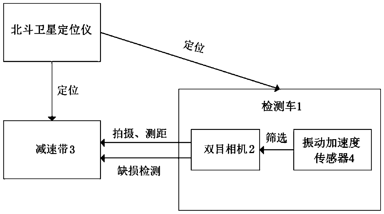
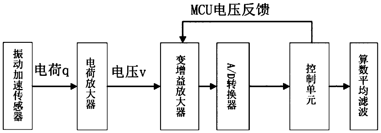
[0047] A defect detection method of a road deceleration belt of the present invention, such as figure 1 As shown, the binocular camera 2 is installed on the upper front of the detection vehicle 1 for real-time collection of road images in front of the detection vehicle 1 and images of the speed bump 3, and the vibration acceleration sensor 4 is installed on the magnetic mounting base, which absorbs On the rear axle of the detection vehicle 1, it is used to collect the vibration signal during the operation of the detection vehicle 1, and then determine whether the detection vehicle 1 passes the deceleration belt 3. The rotary encoder is installed on the rear wheel side of the detection vehicle 1, which can collect Stable speed information, Beidou satellite locator and industrial computer are i...


PUM


Abstract

The invention discloses a defect detection method for a road deceleration strip. The method includes: firstly, obtaining a road image of deceleration strip information; separating a deceleration stripcontour image from the road image; obtaining a grayscale deceleration strip contour image and a grayscale road image without a deceleration strip, then solving a gradient map of the grayscale deceleration strip contour image, further solving an edge line between color blocks, and when the edge line is between a yellow block and a black block, obtaining that the deceleration strip corresponding tothe gradient map is an intact deceleration strip; when the obtained edge line is an edge line between a yellow block, a defective color block and a black block, obtaining a yellow block image, a defect color block image and a black block image, and numbering the low block image, the defect color block image and the black block image in sequence. In this way, gray value comparison in the next stepis facilitated; the total defect number, the defect yellow block number and the defect black block number are finally solved through color lump colors at two ends of defect color lump; and the operation efficiency is high, and the potential harm to vehicles and personnel caused by the defects of the road deceleration strip is avoided.

Description

technical field [0001] The invention relates to the field of road detection, in particular to a defect detection method of a road deceleration belt. Background technique [0002] As an important traffic facility on the road, the speed bump can make the road surface slightly arched to achieve the purpose of vehicle deceleration. The most common speed bump is a speed bump with black blocks and yellow blocks alternated. The working conditions of the speed bump are relatively harsh, and are often damaged due to vibration, shock, sun exposure and aging. This will expose the nails when the speed bump is installed, causing potential harm to vehicles and personnel, which has seriously affected traffic safety. installation. [0003] At present, the existing technical solutions for the speed bumps with black blocks and yellow blocks alternately use machine learning methods, based on convolutional neural networks, to judge whether there are speed bumps in the road and whether they are...

Claims


Application Information

Patent Timeline
IPC IPC(8): G06T7/00G06T7/13
CPCG06T7/0002G06T7/13G06T2207/10004G06T2207/30256
Inventor 王建锋郑好乔盼赵慧婷董学恒张照震郑涛吴学勤
Owner CHANGAN UNIV
Learn More