Time difference estimation method and device for linear frequency modulation signals

A technology of linear frequency modulation signal and time difference estimation, which is applied in the direction of measuring device, frequency modulation carrier system, modulated carrier system, etc., and can solve the problems of reduced precision of time difference estimation

Inactive Publication Date: 2020-02-18
SOUTHWEST CHINA RES INST OF ELECTRONICS EQUIP
View PDF2 Cites 6 Cited by
  • Summary
  • Abstract
  • Description
  • Claims
  • Application Information

AI Technical Summary

Problems solved by technology

However, this method needs to accurately obtain the cycle frequency of the chirp signal, and when there is a cycle frequency error, the accuracy of time difference estimation will be significantly reduced

Method used


Image

  • Time difference estimation method and device for linear frequency modulation signals
  • Time difference estimation method and device for linear frequency modulation signals
  • Time difference estimation method and device for linear frequency modulation signals

Examples


Embodiment 1

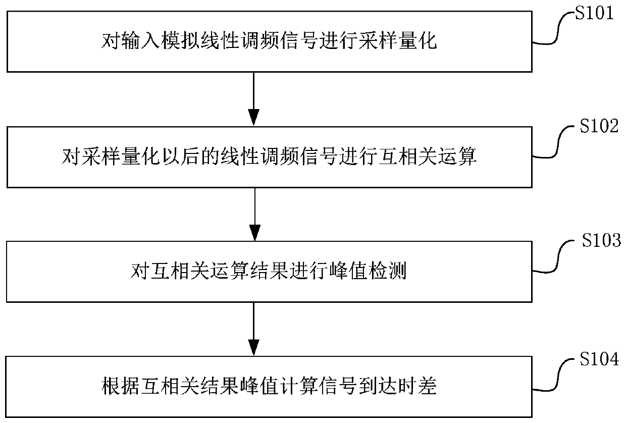
[0029] Such as figure 1 Shown, the time difference estimation method of chirp signal, comprises the following steps:

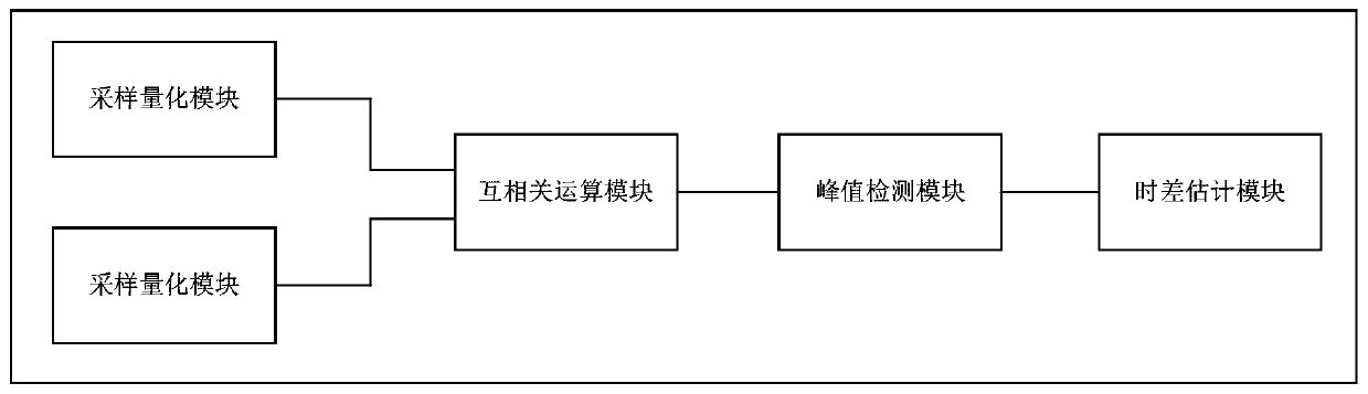
[0030] In step S101: each receiving processing channel in the device samples and quantizes the input analog chirp signal respectively to obtain N sampling points; N is a natural number greater than 0;

[0031] In step S102: performing a cross-correlation operation on the chirp signals sampled and quantized by different receiving processing channels, and sorting the obtained cross-correlation operation results to obtain a cross-correlation result sequence;

[0032] In step S103: carry out peak detection to cross-correlation operation result sequence, search for the maximum value of cross-correlation result, obtain the serial number corresponding to cross-correlation result maximum value;

[0033] In step S104: calculate the signal arrival time difference according to the serial number corresponding to the maximum value of the cross-correlation result.

[0034...

Embodiment 2

[0055] Preferably, the cross-correlation operation in method step S102 is realized by FFT algorithm; FFT algorithm has high calculation efficiency and fast operation speed, and can meet the requirement of real-time time difference estimation. The FFT algorithm refers to Fast Fourier Transform, that is, Fast Fourier Transform.


PUM


Abstract

The invention relates to the field of signal detection and estimation, and discloses a time difference estimation method and device for a linear frequency modulation signal, and the method comprises the steps that a sampling quantification module carries out the sampling quantification of the received linear frequency modulation signal, and then a cross-correlation module carries out the cross-correlation operation of the sampled and quantified linear frequency modulation signal; a peak value detection module performs peak value detection on the cross-correlation operation result, detects themaximum result value, and obtains a corresponding serial number; and finally, a time difference estimation module calculates the arrival time difference of the linear frequency modulation signal according to the serial number. According to the method, the time difference of the arrival signals can be accurately estimated without priori information such as the cyclic frequency of the linear frequency modulation signals, so that the method can also be applied to a non-cooperative signal environment; the method and the device provided by the invention can be used for high-precision measurement oflinear frequency modulation signal time difference in the fields of radar, communication, sonar, electronic warfare and the like, and provide a basis for passive time difference positioning.

Description

technical field [0001] The invention relates to the field of signal detection and estimation, in particular to a time difference estimation method and device for linear frequency modulation signals. Background technique [0002] Using time difference information for target location is a widely used passive location method. This method uses multiple receiving stations at different locations to receive radiation source signals, and realizes radiation source location by estimating the time difference between received signals. Time difference positioning has the characteristics of high positioning accuracy and strong anti-interference ability. As a common signal form, chirp signal has been widely used in many fields such as radar, communication, sonar and electronic warfare. Based on the above reasons, the time difference estimation of chirp signal is of great significance. [0003] At present, the time difference estimation methods of chirp signals are mainly divided into two...

Claims


Application Information

Patent Timeline
Patent Type & Authority Applications(China)
IPC IPC(8): H04L27/14H04L27/227G01S5/06G01S5/22
CPCH04L27/14H04L27/227G01S5/06G01S5/22
Inventor 王茂汶周涛钟欣刘静娴陈智宇
Owner SOUTHWEST CHINA RES INST OF ELECTRONICS EQUIP
Why Eureka
Try Eureka