Chuck for tightening arm machining

A chuck and disk body technology, applied in metal processing equipment, metal processing mechanical parts, manufacturing tools, etc., can solve the problems of inconvenient installation of high-precision machining shaft holes, and achieve the purpose of ensuring accuracy, ensuring machining accuracy, and improving machining accuracy. Effect

Pending Publication Date: 2020-02-21
YUHUAN ZHONGBEN MACHINERY
View PDF1 Cites 0 Cited by
  • Summary
  • Abstract
  • Description
  • Claims
  • Application Information

AI Technical Summary

Problems solved by technology

[0005] The purpose of the present invention is to solve the above-mentioned problems in the prior art, and propose a chuck for tensioning arm processing, which solves the problem of inconvenient installation when machining shaft holes with high precision

Method used


Image

  • Chuck for tightening arm machining
  • Chuck for tightening arm machining
  • Chuck for tightening arm machining

Examples


Embodiment 1

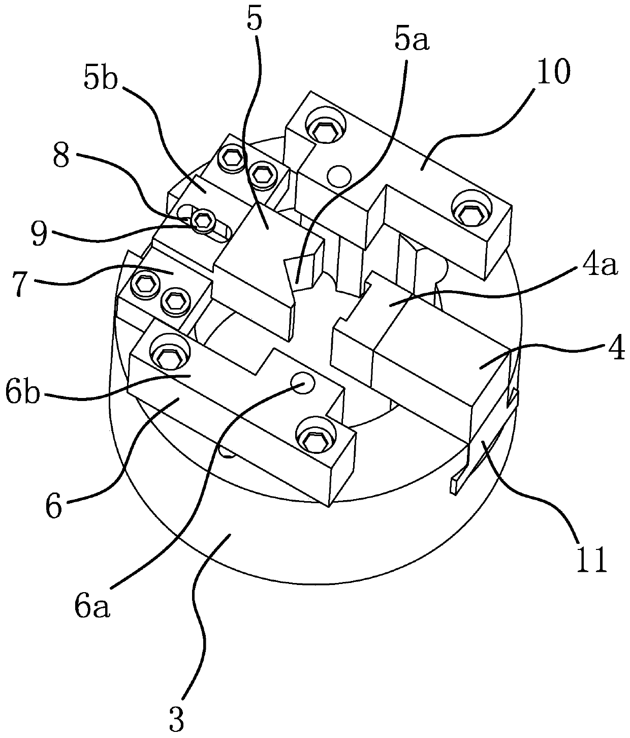
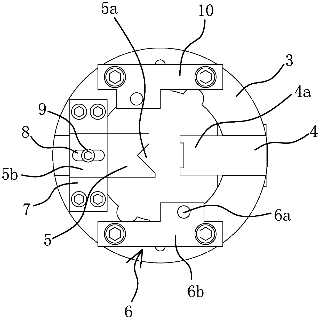
[0035] like figure 2 and image 3 As shown, a chuck for tensioning arm processing includes a disc body 3 and a clamping block 4 slidably connected to one end of the disc body 3 in the radial direction. The end of the disc body 3 is also fixed with a positioning block 5, and the positioning block 5 is located on the sliding path of the clamping block 4. Specifically, the disc body 3 is radially provided with a sliding groove, and a sliding block 11 is slidably disposed in the sliding groove, and the clamping block 4 is fixed on the sliding block 11 by fasteners to realize sliding.

[0036] like figure 2 and image 3 As shown, the end of the disc body 3 where the positioning block 5 is located is also fixed with a mounting block 6 , and the positioning block 5 and the clamping block 4 are located on the same side of the mounting block 6 . One side of the positioning block 5 facing the clamping block 4 is provided with a V-shaped groove 5a, and one side of the V-shaped groo...

Embodiment 2

[0044] The structure and principle of this embodiment are basically the same as that of Embodiment 1, the difference is that in this embodiment, the installation block 6 is provided with a mounting column, the axis of the mounting column is perpendicular to the disc body 3, and the V-shaped groove 5a The groove walls on both sides are parallel to the axis of the mounting column. The counterweight 10 has the same shape and size as the installation block 6 , and the counterweight 10 is provided with the same protrusion as the installation post, and the counterweight 10 and the installation block 6 are centrally symmetrical.

Embodiment 3

[0046] The structure and principle of this embodiment are basically the same as that of Embodiment 1, the difference is that in this embodiment, the clamping block 4 is made of flexible material, and the clamping part 4a is the part of the clamping block 4 facing the positioning block 5 . The flexible material can be nylon, rubber or plastic, etc.


PUM


Abstract

The invention provides a chuck for tightening arm machining, and belongs to the technical field of machinery. The problem of inconvenient mounting when shaft holes are machined with high precision issolved. The chuck includes a disc body and a clamping block slidably connected to one end of the disc body in the radial direction, a positioning block and a mounting block are further fixed to one end of the disc body, the positioning block is located on a sliding path of the clamping block, a V-shaped groove is formed in the side, facing the clamping block, of the positioning block, and the positioning block and the clamping block are arranged on the same side of the mounting block, a mounting hole is formed in the mounting block, the center line of the mounting hole is perpendicular to thedisc body, and the grooves walls on the two sides of the V-shaped groove are parallel to the center line of the mounting hole respectively. The chuck has the advantages of being high in machining accuracy, convenient to mount, simple in structure, and convenient to produce.

Description

technical field [0001] The invention belongs to the technical field of hydraulic chucks, and relates to a chuck, in particular to a chuck for tensioning arm processing. Background technique [0002] Motorcycles currently on the market basically use chain transmission, and the chain will loosen after a long time of use, resulting in blocked transmission. For this reason, an automatic tensioning device will be installed on the motorcycle, and the automatic tensioning device will be used on the chain to use the automatic tensioning device. It remains taut. The automatic tensioning device basically includes a tensioning arm assembly, a tensioning spring and a tensioning wheel. The structure of the tensioning arm assembly is as follows: figure 1 As shown, it includes a tensioning arm 1 that is basically in the shape of a long thin plate. The middle part of the tensioning arm 1 is provided with a shaft hole 1c, and the outer edges of both sides of the middle part of the tensionin...

Claims


Application Information

Patent Timeline
Patent Type & Authority Applications(China)
IPC IPC(8): B23Q3/12
CPCB23Q3/12
Inventor 高喜高源浩姜继发
Owner YUHUAN ZHONGBEN MACHINERY
Why Eureka
Try Eureka