Crankshaft automatic positioning and clamping mechanism

An automatic positioning and clamping mechanism technology, applied in positioning devices, metal processing machinery parts, clamping, etc., can solve the problems of low efficiency, cumbersome operation, manual positioning and clamping, etc., and achieve low labor intensity, good effect, The effect of avoiding hard collisions

Inactive Publication Date: 2011-05-11
TIANJIN BAOLAI PRECISION MACHINERY
View PDF7 Cites 0 Cited by
  • Summary
  • Abstract
  • Description
  • Claims
  • Application Information

AI Technical Summary

Problems solved by technology

The structure of the existing clamping mechanism is relatively simple, the workpiece needs to be positioned and clamped manually when positioning and clamping, the operation is cumbersome and the efficiency is low

Method used


Image

  • Crankshaft automatic positioning and clamping mechanism
  • Crankshaft automatic positioning and clamping mechanism
  • Crankshaft automatic positioning and clamping mechanism

Examples


Embodiment Construction

[0019] Embodiments of the present invention are described in further detail below in conjunction with the accompanying drawings:

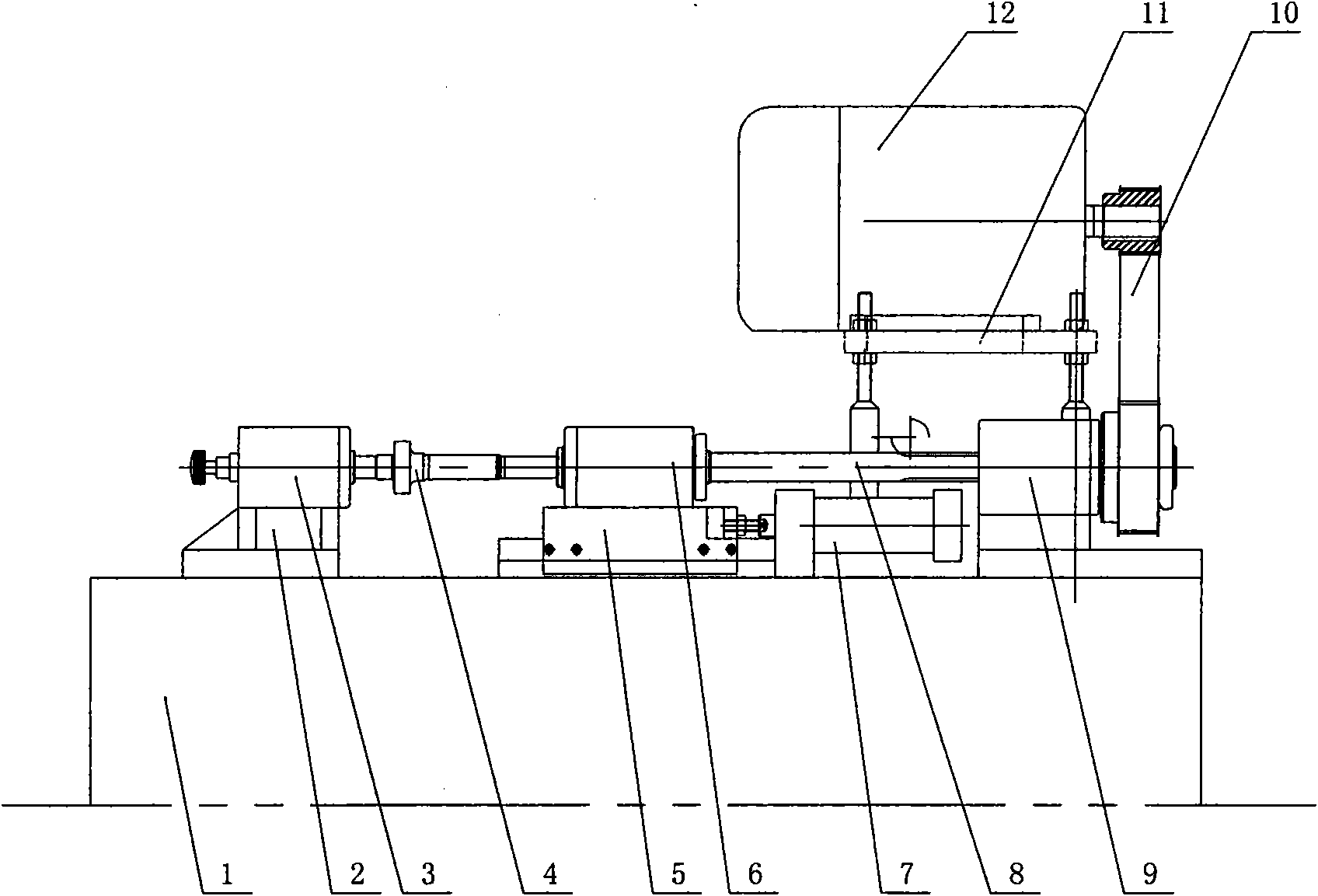
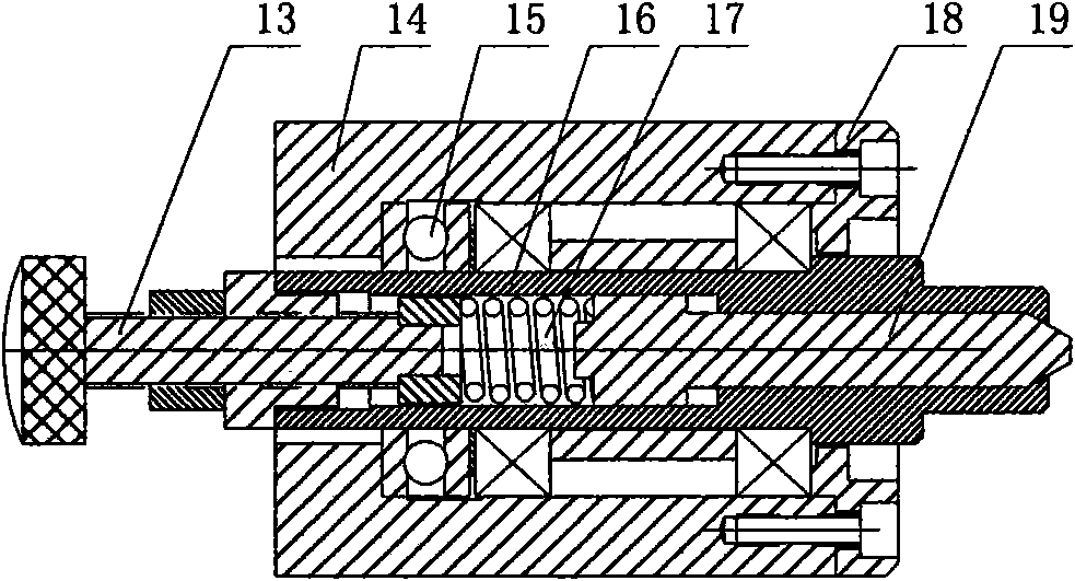
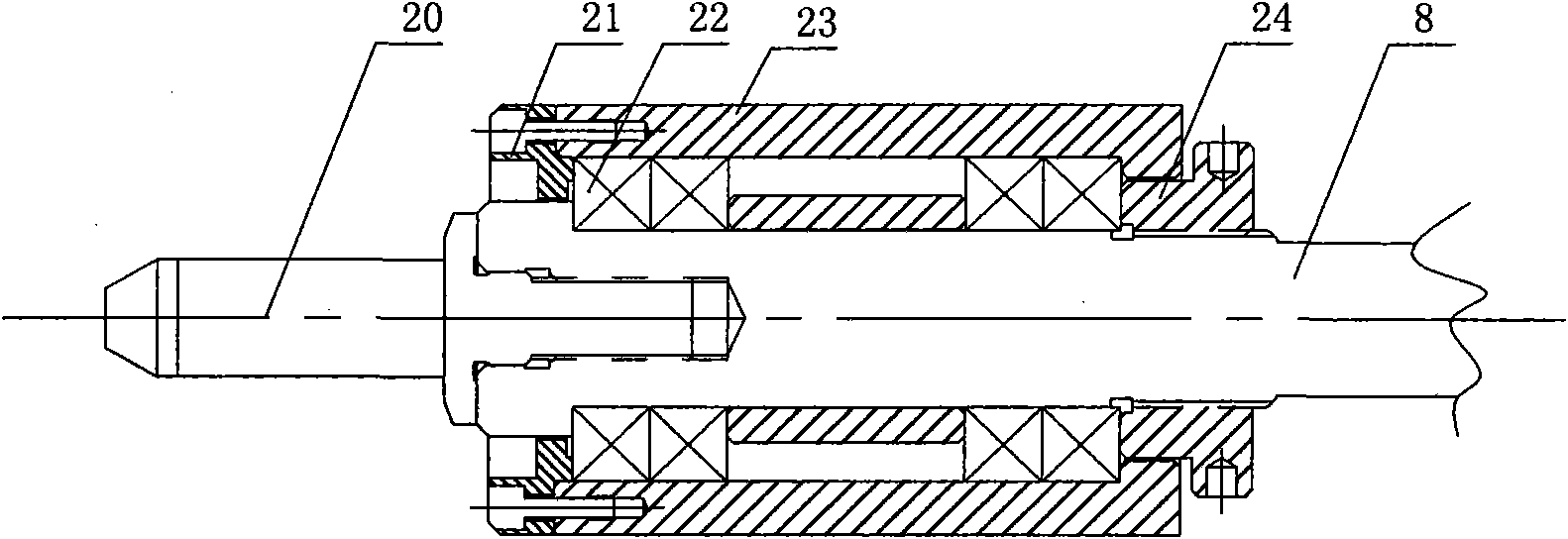
[0020] A crankshaft automatic positioning and pressing mechanism is innovative in that it is composed of a center positioning mechanism 3 installed on a machine base 1, a pressing and positioning mechanism 6, a driving mechanism 9, a transmission mechanism 10, and a motor 12. The center positioning mechanism is installed on the machine base through the fixed base 2, and the pressing positioning mechanism is installed on the machine base through a moving base 5, which is driven by a hydraulic cylinder 7 fixed on the machine base. The pressing positioning mechanism and the central positioning mechanism are arranged at intervals and respectively installed with opposite rotating tops for clamping the workpiece 4 . The driving mechanism is fixed on the machine base through the mounting seat and its output shaft 8 is linked with the top of the pressing a...


PUM


Abstract

The invention relates to a crankshaft automatic positioning and clamping mechanism which is characterized by being composed of a center positioning mechanism, a clamping and positioning mechanism, a driving mechanism, a transmission mechanism and a motor which are arranged on a base, wherein the center positioning mechanism is arranged on the base through a fixed seat; the clamping and positioning mechanism is arranged on the base through a movable seat, and the clamping and positioning mechanism and the center positioning mechanism are arranged at an interval, and are provided with opposite rotating tips respectively; the driving mechanism is fixedly arranged on the base through a fitting seat, and the output shaft of the driving mechanism and the tip of the clamping and positioning mechanism are linked; and the input end of the driving mechanism is driven by the motor through the transmission mechanism. The crankshaft automatic positioning and clamping mechanism is suitable for the fabricating characteristics of a Danfoss crankshaft, and is convenient to operate. The crankshaft automatic positioning and clamping mechanism has the advantages of stable and efficient positioning and clamping operation, low labor intensity, and the like, thereby greatly lowering the processing cost and increasing the yield.

Description

technical field [0001] The invention relates to a mechanical processing device, in particular to a crankshaft automatic positioning and pressing mechanism. Background technique [0002] At present, when using ordinary machine tools to process the outer diameter (short axis, long axis) and chamfering of Danfoss crankshaft, the workpiece needs to be coaxially positioned and clamped on the clamping mechanism. The structure of the existing clamping mechanism is relatively simple, and the workpiece needs to be manually positioned and clamped when positioning and clamping, which is cumbersome to operate and low in efficiency. Contents of the invention [0003] The purpose of the present invention is to overcome the deficiencies of the prior art, and provide a crankshaft automatic positioning and pressing mechanism, which can quickly and accurately realize automatic positioning and clamping of workpieces, and is extremely convenient to operate. [0004] The present invention sol...

Claims


Application Information

Patent Timeline
Patent Type & Authority Applications(China)
IPC IPC(8): B23Q3/00
Inventor 崔健涛崔文来
Owner TIANJIN BAOLAI PRECISION MACHINERY
Why Eureka
Try Eureka