
Positioning and pressing device

A pressing device and positioning convex technology, which is applied in auxiliary devices, workpiece clamping devices, transportation and packaging, etc., can solve the problems that the movement of the connecting rod mechanism is difficult to achieve consistency, uncompressed, and inconvenient to operate.

Pending Publication Date: 2021-03-30
YASKAWA SHOUGANG ROBOT CO LTD
View PDF1 Cites 1 Cited by
  • Summary
  • Abstract
  • Description
  • Claims
  • Application Information

AI Technical Summary

Problems solved by technology

Therefore, two pressing mechanisms are used to respectively compress the two ends of the workpiece. Driven by the two independent and unrelated driving mechanisms, it is difficult to achieve the same movement of the two sets of connecting rod mechanisms, and it is easy to appear that one end of the workpiece has been crushed. Compressed, but the other end is not compressed, and the size of the material thickness in the left and right directions of the part has a greater impact
Moreover, with the above scheme, it is necessary to control two hydraulic cylinders or pneumatic cylinders, which is inconvenient to operate

Method used


Image

  • Positioning and pressing device
  • Positioning and pressing device
  • Positioning and pressing device

Examples


Embodiment Construction

[0092] In order to enable those skilled in the art to better understand the technical solutions in the present invention, the technical solutions in the embodiments of the present invention will be clearly and completely described below in conjunction with the drawings in the embodiments of the present invention. Obviously, the described The embodiments are only some of the embodiments of the present invention, not all of them. Based on the embodiments of the present invention, all other embodiments obtained by persons of ordinary skill in the art without making creative efforts shall fall within the protection scope of the present invention.

[0093] It should be noted that when an element is referred to as being “disposed on” another element, it may be directly on the other element or there may also be an intervening element. When an element is referred to as being "connected to" another element, it can be directly connected to the other element or intervening elements may a...


PUM


Abstract

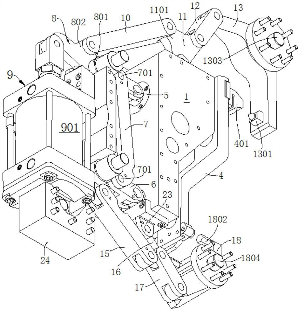
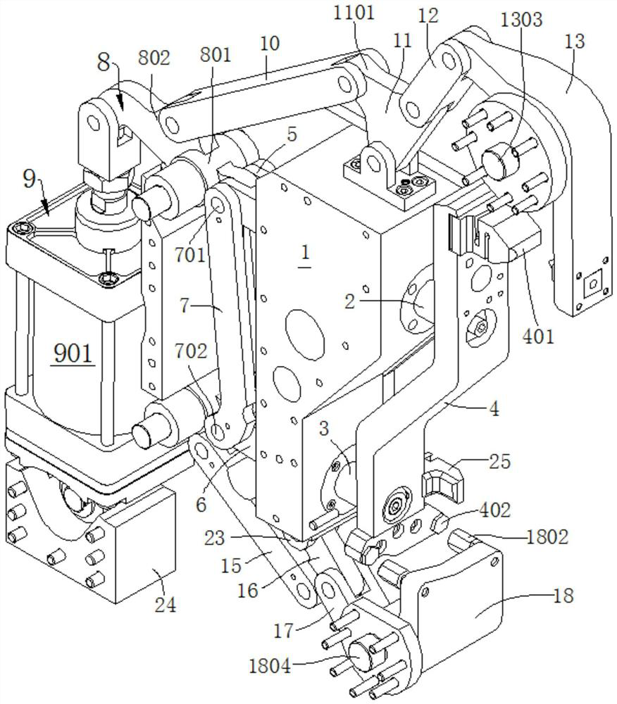
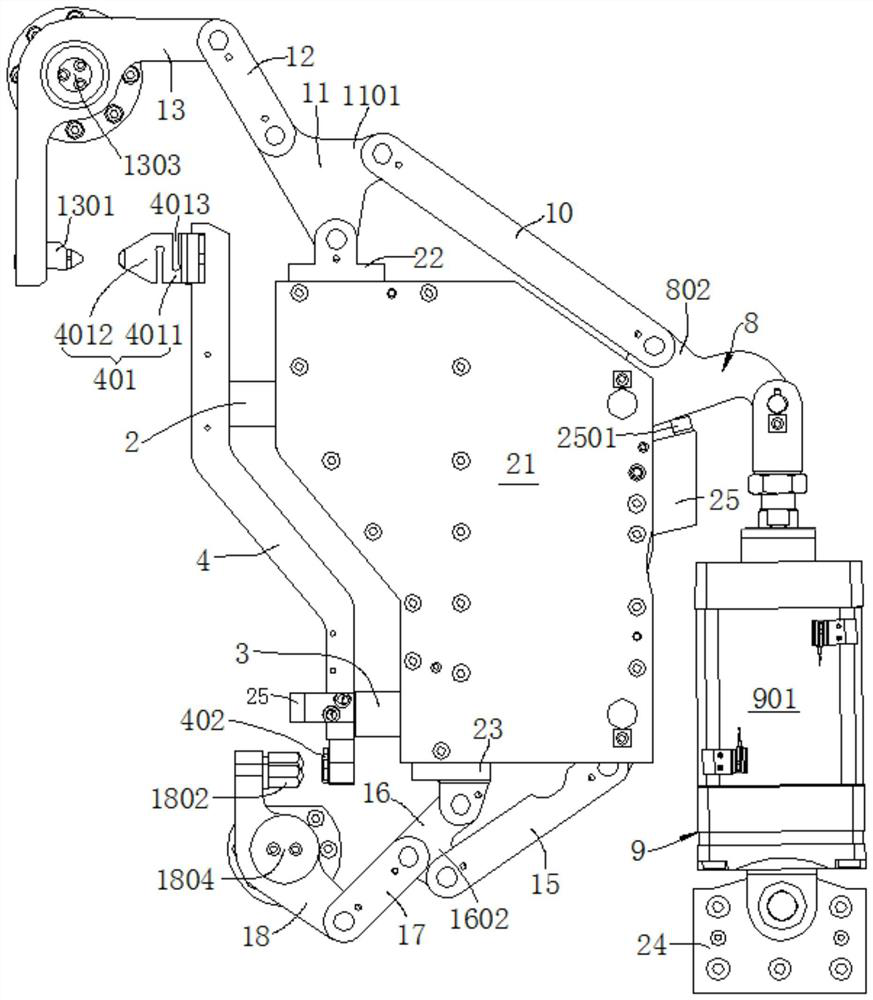
The invention provides a positioning and pressing device. The positioning and pressing device comprises a base, a first connecting block, and a second connecting block, wherein the base is provided with two channels, and two rod bodies are movably arranged in the two channels in a penetrating mode; one ends of the rod bodies are connected with a crank arm provided with first and second positioningprotruding points, and the other ends of the rod bodies are connected with connecting rods; a middle connecting rod is connected between the two connecting rods, and connecting points between the middle connecting rod and the two connecting rods are first and second pivoting points; the first connecting block is provided with a first connecting lug, and the two ends of the first connecting blockare connected with the first pivoting point and a power mechanism correspondingly; the first connecting lug is connected with a first pressing piece, and the first pressing piece is provided with a first pressing protruding point matched with the first positioning protruding point; and the second connecting block is provided with two second connecting lugs, one second connecting lug is connected with the second pivoting point, the other second connecting lug is connected with a second pressing piece, and the second pressing piece is provided with a second pressing protruding point matched withthe second positioning protruding point. According to the positioning and pressing device, the two ends of a workpiece can be positioned and pressed at the same time through one power mechanism, thepositioning and pressing effect is good, and operation is easy and convenient.

Description

technical field [0001] The invention relates to the field of workpiece positioning and pressing equipment, in particular to a positioning and pressing device. Background technique [0002] The statements in this section only provide background information related to the present disclosure and may not constitute prior art. [0003] When welding the workpieces involved in the frame, such as longitudinal beams, beams, left and right suspensions, and various torsion beam rear axle suspension arms, it is necessary to position and press them to reduce the impact of part errors. To make its position fixed, easy to operate. [0004] The pressing mechanism in the prior art generally can only realize single-end pressing, that is, one pressing mechanism can only press and fix one end of the workpiece. Therefore, it is usually necessary to adopt two pressing mechanisms to respectively press the two ends of the workpiece. [0005] Since each pressing mechanism is configured with a dri...

Claims


Application Information

Patent Timeline
IPC IPC(8): B23K37/04B25B11/00
CPCB23K37/04B25B11/00B23K2101/006
Inventor 樊哲田心宽李鹏
Owner YASKAWA SHOUGANG ROBOT CO LTD
Learn More