
Crankshaft connecting rod positioning and pressing structure in electric actuator pull rod adjusting structure

A technology of electric actuators and crankshaft connecting rods, applied in hand-held tools, manufacturing tools, etc., can solve the problems of small space range, difficult installation, large assembly errors, etc., and achieve simple and reasonable structural design, good positioning and pressing effect, The effect of meeting the needs of use

Pending Publication Date: 2020-02-28
HANGZHOU GAOPIN AUTOMATION EQUIP
View PDF11 Cites 0 Cited by
  • Summary
  • Abstract
  • Description
  • Claims
  • Application Information

AI Technical Summary

Problems solved by technology

[0002] The existing structure has the following defects: the cylinder is directly pressed with the product through the extension rod, resulting in loose pressing, easy loosening, vertical pressing, small space range, difficult installation, resulting in assembly errors
Although this patent can fine-tune the jaws by rotating the thread, the pressing is not tight, it is not easy to install, and the assembly error is large, so it still has the above defects

Method used


Image

  • Crankshaft connecting rod positioning and pressing structure in electric actuator pull rod adjusting structure
  • Crankshaft connecting rod positioning and pressing structure in electric actuator pull rod adjusting structure
  • Crankshaft connecting rod positioning and pressing structure in electric actuator pull rod adjusting structure

Examples


Embodiment Construction

[0017] The present invention will be further described in detail below in conjunction with the accompanying drawings and examples. The following examples are explanations of the present invention and the present invention is not limited to the following examples.

[0018] Example.

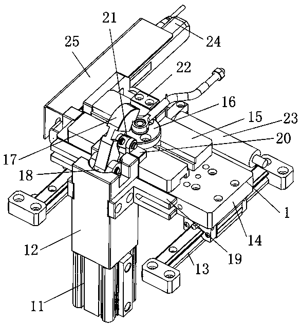
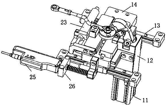
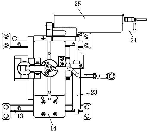
[0019] see Figure 1 to Figure 3 The crankshaft connecting rod positioning and pressing structure in the pull rod adjustment structure of the electric actuator in this embodiment includes a crankshaft connecting rod positioning and pressing mechanism 1, and the crankshaft connecting rod positioning and pressing mechanism 1 includes a crankshaft connecting rod positioning and pressing cylinder 11 and a cylinder seat 12. , guide rail 13, sliding seat 14, adjusting seat 15, positioning seat 16, pressing head 17, connecting rod 18, fixed block 19, V-shaped block 20 and connecting rod 21, and the crankshaft connecting rod positioning pressing gas 11 cylinder is fixed on On the cylinder block 12, the ex...


PUM


Abstract

The invention relates to a crankshaft connecting rod positioning and pressing structure in an electric actuator pull rod adjusting structure, and belongs to the field of electric actuators. The crankshaft connecting rod positioning and pressing structure comprises a crankshaft connecting rod positioning and pressing mechanism, the crankshaft connecting rod positioning and pressing mechanism comprises a crankshaft connecting rod positioning and pressing air cylinder, an air cylinder seat, a guide rail, a sliding seat, an adjusting seat, a positioning seat, a pressing head, a fixed block, a V-shaped block and a connecting rod, the crankshaft connecting rod positioning and pressing air cylinder is fixed to the air cylinder seat, an extension rod of the crankshaft connecting rod positioning and pressing air cylinder is connected with the pressing head, the fixed block is connected with the sliding seat, the sliding seat is slidably connected with the guide rail, the adjusting seat is fixedto the sliding seat, the positioning seat is installed on the adjusting seat, the V-shaped block is connected with the air cylinder seat, one end of the connecting rod is connected with the pressinghead through a pin, and the other end of the connecting rod is connected with the V-shaped block. According to the crankshaft connecting rod positioning and pressing structure, the design is simple and reasonable, safety and reliability are achieved, assembly is convenient, the positioning and pressing effect is good, and using requirements are met.

Description

technical field [0001] The invention relates to a pressing structure, in particular to a positioning and pressing structure of a crankshaft connecting rod in an electric actuator pull rod adjustment structure, which belongs to the field of electric actuators. Background technique [0002] The existing structure has the following defects: the cylinder is pressed directly with the product through the extending rod, resulting in loose pressing, easy loosening, vertical pressing, small space range, difficult installation, and assembly errors. [0003] The publication date is March 27, 2013, and the Chinese patent publication number 102990568A discloses an invention patent named "a connecting rod pressing device". The patent includes a fixture body, jaws, connecting rods, end plates and an adjusting rod as a force application device. The jaws are hinged on the fixture body, and the driven end of the jaws presses the workpiece. The connecting rod is slidably connected to the fixtu...

Claims


Application Information

Patent Timeline
Patent Type & Authority Applications(China)
IPC IPC(8): B25B27/02
CPCB25B27/026
Inventor 张志刚赵志龙徐顺士李志东
Owner HANGZHOU GAOPIN AUTOMATION EQUIP
Learn More