
Storage battery plastic shell machining and cooling device

A technology of cooling device and battery, applied in battery pack parts, metal processing equipment, battery box/jacket, etc., can solve problems such as inability to cool workpieces

Inactive Publication Date: 2020-02-21
长兴永润机械有限公司
View PDF1 Cites 0 Cited by
  • Summary
  • Abstract
  • Description
  • Claims
  • Application Information

AI Technical Summary

Problems solved by technology

The position of the workpiece and the loading and unloading of the workpiece are determined by the suction cup base and the secondary suction cup that move left and right, but the equipment has the following problems: the water jet cutting machine cannot cool the workpiece during use

Method used

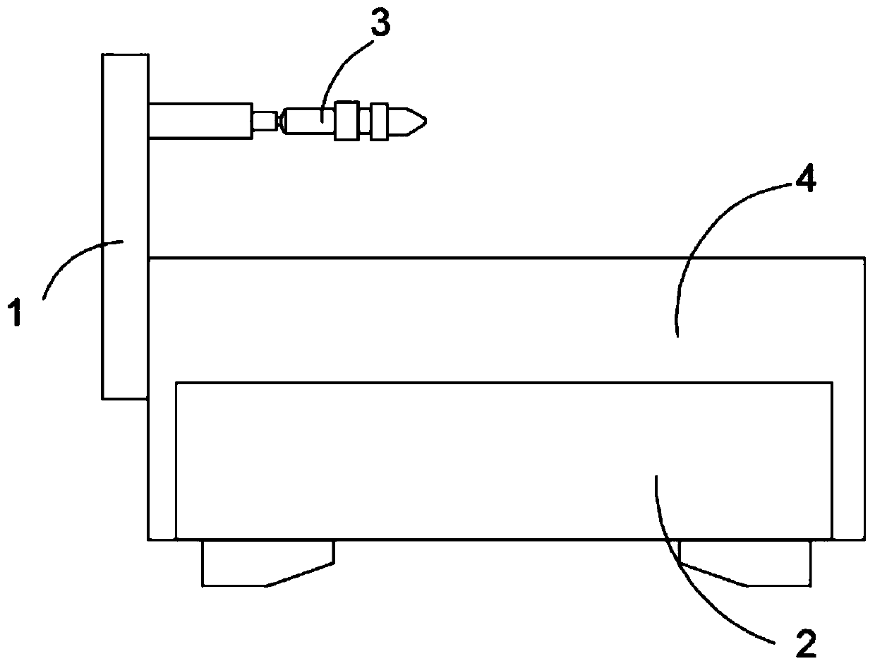
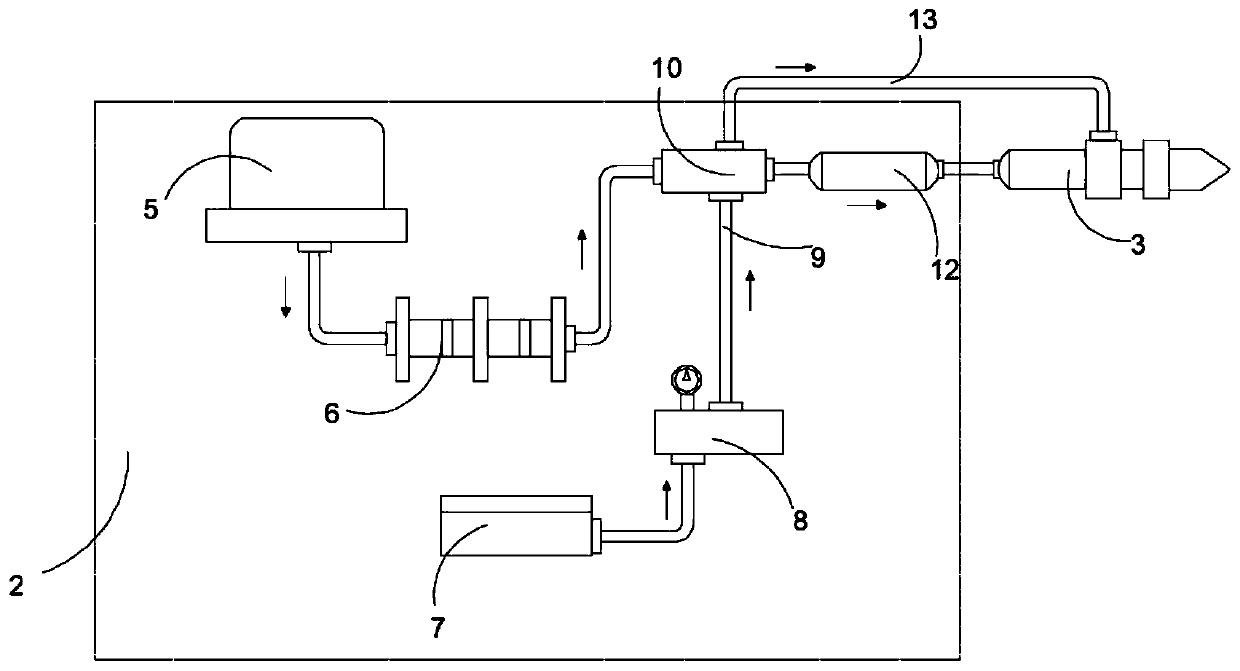

Image

  • Storage battery plastic shell machining and cooling device
  • Storage battery plastic shell machining and cooling device
  • Storage battery plastic shell machining and cooling device

Examples


Embodiment 1

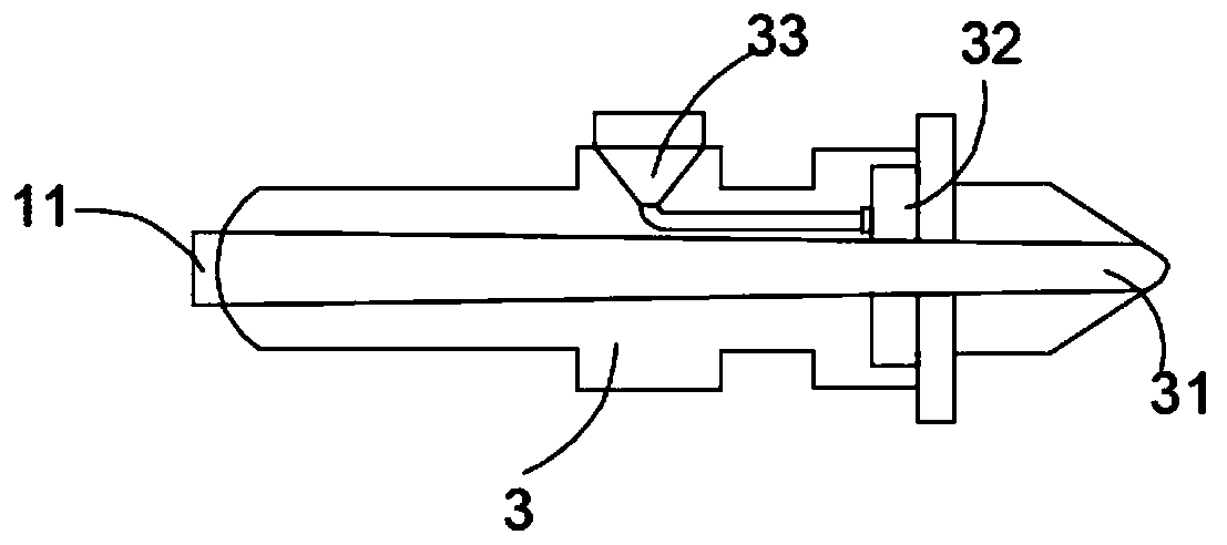
[0025] see Figure 1-4 , the present invention provides the following technical solutions: a battery molded case processing cooling device, including an X-Y axis movable frame 1, a water jet cutting assembly 2, a water jet nozzle 3 and a workbench 4, and the side of the workbench 4 is equipped with an X-Y axis The movable frame 1 is fixedly connected with the water jet nozzle 3 on the X-Y axis movable frame 1, and the water jet cutting assembly 2 is installed inside the working table 4. The water jet nozzle 3 is mainly composed of a water jet cutting pipe 31, a cooling sprinkler 32 and a The spraying water inlet 33 is composed of a water jet cutting pipe 31 installed inside the water jet nozzle 3. One end of the water jet cutting pipe 31 is connected to the outlet of the water jet nozzle 3, and the other end is fixedly connected to the water jet water inlet 11. The water jet nozzle The outer wall of 3 is equipped with a cooling spray inlet 33, and the outer wall of the water j...

Embodiment 2

[0032] like Figure 1 to Figure 4 As shown, the components that are the same as or corresponding to those in the first embodiment are marked with the corresponding reference numerals in the first embodiment. For the sake of simplicity, only the differences from the first embodiment will be described below. The difference between this embodiment two and embodiment one is: as Figure 4 As mentioned above, the sprinkler water inlet 321 is installed on the cooling sprinkler 32, and the sprinkler water inlet 321 is connected to the cooling spray water inlet 33 through a connecting pipe.

[0033] The sprinkler water inlet 321 is connected to the cooling spray inlet 33 through a connecting pipe, so that the water entering the cooling spray inlet 33 flows through the connecting pipe to the cooling sprinkler 32, thereby cooling the plastic case of the cold battery spray.

[0034]The working principle and application process of the present invention: the present invention places the p...


PUM


Abstract

The invention discloses a storage battery plastic shell machining and cooling device in the field of storage battery machining. The storage battery plastic shell machining and cooling device comprisesan X-Y-axis movable frame, a water knife cutting assembly, a water knife spraying nozzle and a workbench. The X-Y-axis movable frame is arranged on the lateral side of the workbench and fixedly connected with the water knife spraying nozzle. The water knife cutting assembly is installed in the workbench. The water knife spraying nozzle serves as a cooling apparatus, and an electromagnetic controlvalve A, an electromagnetic control valve B and an electromagnetic control valve C are controlled by a controller, so that water in a water supplying device is directly input to a cooling sprayer onthe water knife spraying nozzle through the work of a water pump, the cooling sprayer has a spraying function, and the after-machining cooling of a storage battery plastic shell is realized; the storage battery plastic shell has many burrs after die machining, the water knife spraying nozzle can be controlled through the X-Y-axis movable frame, and the bronze drum water knife spraying nozzle sprays out a water knife to clean up the burrs on the storage battery plastic shell.

Description

technical field [0001] The invention belongs to the technical field of battery plastic case processing, and in particular relates to a cooling device for battery plastic case processing. Background technique [0002] Various equipment used in the battery production process. The structure of the battery is composed of shell, upper cover, pole plate, separator, bus bar, pole, bridge protection plate, terminal and other components. After the battery casing is molded, it needs to be cooled. [0003] Authorized notification number CN209552806U is a Chinese invention patent, which discloses a multifunctional water jet cutting machine, including a cutting platform, a longitudinal guide rail, a beam, a left and right moving seat, a water jet fixing seat, and a water jet. It is characterized in that the longitudinal guide rail Floating out of the cutting platform, a transmission mechanism is set under the longitudinal guide rail outside the floating cutting platform, a main suction...

Claims


Application Information

Patent Timeline
Patent Type & Authority Applications(China)
IPC IPC(8): B24C1/08B24C9/00H01M2/02
CPCB24C1/083B24C9/00H01M50/10Y02E60/10
Inventor 沈永华
Owner 长兴永润机械有限公司
Learn More