Supercharge Your Innovation With Domain-Expert AI Agents!

Bare tire bead winding method and tire bead winding system

A bead and winding ring technology, applied in the field of tire production auxiliary equipment, can solve the problems of waste, low production efficiency, waste of manpower, etc., and achieve the effects of high efficiency, high winding stability, and no material waste.

Inactive Publication Date: 2020-02-21
LINK-ASIA SMART TECH (SUZHOU) CO LTD
View PDF6 Cites 1 Cited by
  • Summary
  • Abstract
  • Description
  • Claims
  • Application Information

AI Technical Summary

Problems solved by technology

In the existing bead, the strip is wound onto the bare bead through the bead winding system. Specifically, the ring part in the bead winding system is driven by the driving device to rotate. During this process, the winding device is wrapping the strip While winding on the bare bead, the strip is wound on the roller part set on the end surface of the winding ring for storage. The strip will be wound on the roller part for multiple turns. After the strip is cut by the cutting mechanism, the winding ring continues to rotate And release the multi-turn strip that has been wound on the roller part, so that the strip stored on the roller part continues to wrap the bare tire bead, but this operation requires at least one manual to pull the strip head wound on the roller part If the tape is pulled out and pasted on the bare bead, due to the high viscosity of the tape, the tape wound on the roller part for multiple turns will stick together, so that the pulling action cannot be completed quickly, which wastes manpower and the production efficiency is not high. low stability
[0004] Under normal circumstances, before the material head of the strip is manually pulled out and pasted on the bare bead, a part of the material will be subtracted to ensure the quality of the joint, which will cause waste

Method used


Image

  • Bare tire bead winding method and tire bead winding system
  • Bare tire bead winding method and tire bead winding system
  • Bare tire bead winding method and tire bead winding system

Examples


Embodiment Construction

[0041] The following will clearly and completely describe the technical solutions in the embodiments of the present invention with reference to the accompanying drawings in the embodiments of the present invention. Obviously, the described embodiments are only some, not all, embodiments of the present invention. Based on the embodiments of the present invention, all other embodiments obtained by persons of ordinary skill in the art without creative efforts fall within the protection scope of the present invention.

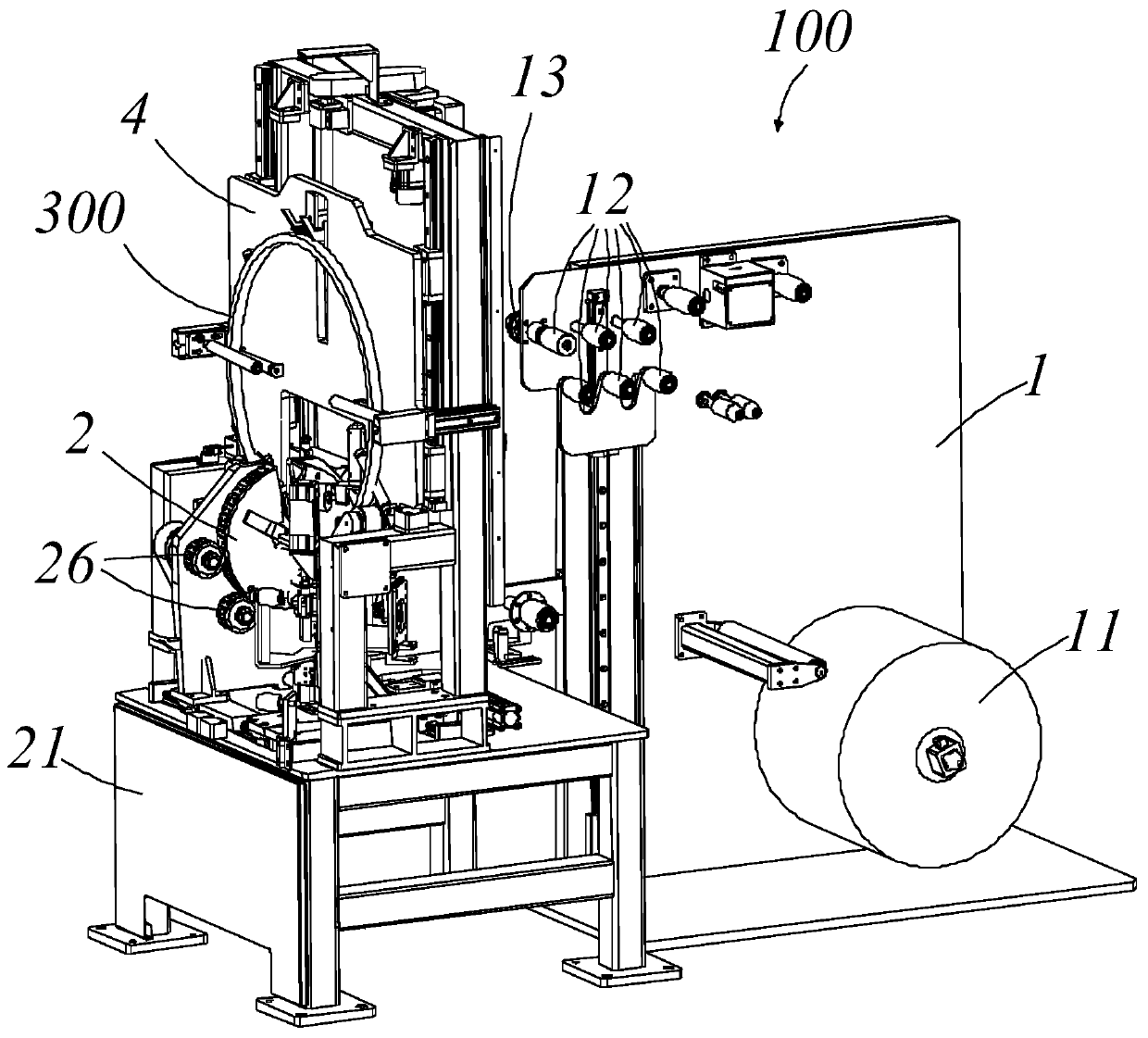
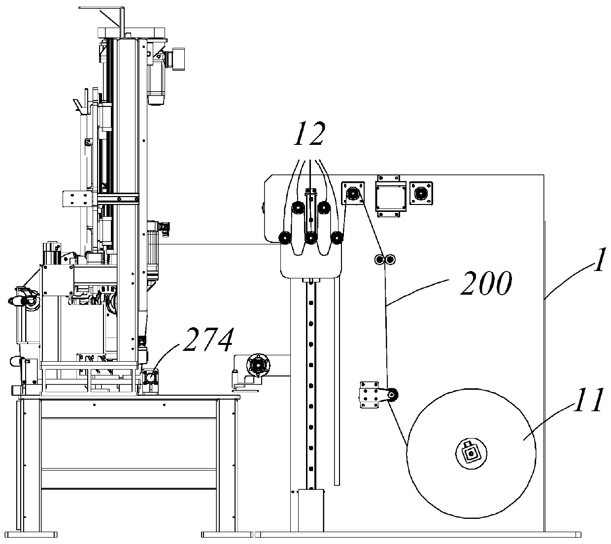
[0042] Such as Figure 1-2 As shown, the present invention discloses a bead winding system 100 for helically winding a rubber strip 200 onto a bare bead 300 to form a bead. The bead winding system 100 includes a feeding device 1 , a winding ring device 2 , a second drive mechanism 4 for fixing and driving the bare bead 300 to move and rotate, and a cutting mechanism 5 for cutting the strip 200 . In this embodiment, the strip 200 is a strip-shaped rubber strip rein...


PUM


Abstract

The invention provides a bare tire bead winding method. The bare tire bead winding method comprises the following steps that a storage roller wound with a strip is reversely rotated for discharging, and the strip is conveyed and fed towards a roller part; when a material head of the strip is conveyed to the roller part, the roller part is rotated to automatically wind the strip with the required length to the roller part, and the tail part of the strip with a certain length is reserved below a bare tire bead; when a winding ring part is positioned at the initial position, the bare tire bead isinserted into the winding ring part from a notch part and is attached to the tail part of the strip, and the end face of the bare tire bead is perpendicular to the end face of the winding ring part;and meanwhile, the winding ring part and the bare tire bead are rotated so as to wind the strip to the bare tire bead. The invention further provides a tire bead winding system for winding by utilizing the bare tire bead winding method. Therefore, the bare tire bead winding method and system can realize full automation, material waste is avoided in the whole process, the winding stability is high,and the efficiency is high.

Description

technical field [0001] The invention relates to the field of tire production auxiliary equipment, in particular to a bare bead winding method and a bead winding system. Background technique [0002] As a component of the tire, the bead supports the fastening force between the tire and the rim, maintains and seals the air pressure inside the tire, and plays an important role in the cushioning and adjustment safety of the sidewall of the tire. [0003] Generally, the bead includes a bare bead and a strip, wherein the bare bead is a structure formed by arranging single-core glued steel wires according to a specific cross-sectional shape, and its cross-sectional shape is usually roughly hexagonal. In the subsequent process, It is very important to maintain the cross-sectional hexagonal shape. In the existing bead, the strip is wound onto the bare bead through the bead winding system. Specifically, the ring part in the bead winding system is driven by the driving device to rotat...

Claims


Application Information

Patent Timeline
Patent Type & Authority Applications(China)
IPC IPC(8): B29D30/50
CPCB29D30/50
Inventor 郑杰
Owner LINK-ASIA SMART TECH (SUZHOU) CO LTD
Features
  • R&D
  • Intellectual Property
  • Life Sciences
  • Materials
  • Tech Scout
  • Unparalleled Data Quality
  • Higher Quality Content
  • 60% Fewer Hallucinations
Learn More