Train anti-derailing device capable of dynamically monitoring track state
A track state and dynamic monitoring technology, which is applied in transportation and packaging, railway car body parts, railway vehicle shape measuring instruments, etc., can solve problems such as difficult derailment prevention, and achieve the effect of ensuring service life, increasing stability and reducing derailment
- Summary
- Abstract
- Description
- Claims
- Application Information
AI Technical Summary
Problems solved by technology
Method used
Image
Examples
Embodiment 1
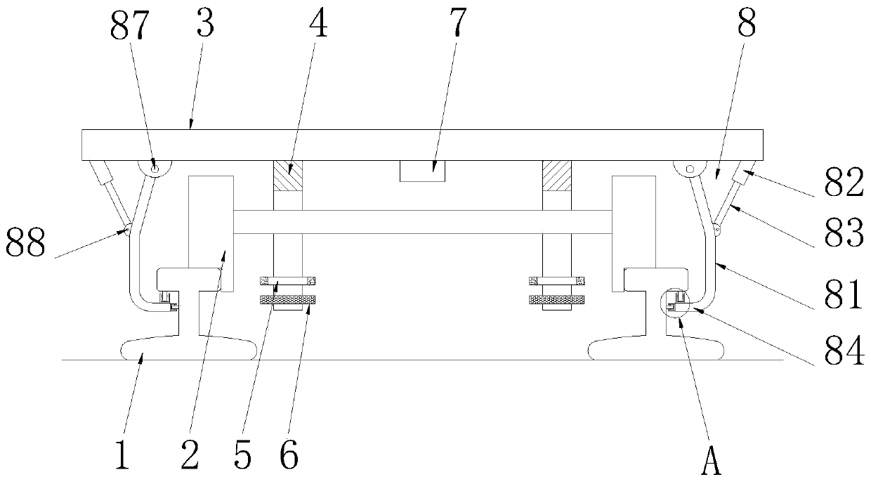
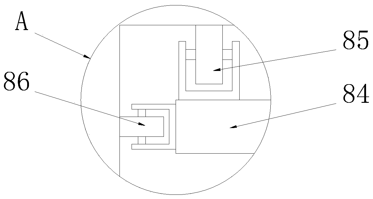
[0024] See Figure 1-2, a driving anti-derailment device that can dynamically monitor the state of the track, including a track 1 and a chassis mechanism 3, the bottom end of the chassis mechanism 3 is fixedly connected with a wheel mechanism 2 that matches the track 1, and the bottom end of the chassis mechanism 3 is left and right Both sides are symmetrically fixedly connected with a bracket 4 matching with the wheel mechanism 2, the bracket 4 is a U-shaped structure, two brackets 4 are arranged on the inner side of the track 1, the bracket 4 is sleeved on the outside of the wheel mechanism 2, and the bracket 4 The side wall of the inner cavity is fixedly connected with a laser displacement sensor 5 matched with the wheel mechanism 2 and a laser profile sensor 6 matched with the wheel mechanism 2, and the laser displacement sensor 5 is arranged above the laser profile sensor 6. The middle part of the bottom end of the chassis mechanism 3 is fixedly equipped with a control de...
Embodiment 2
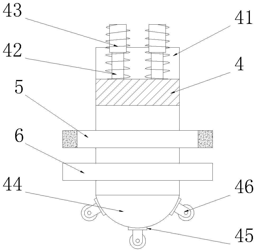
[0026] See Figure 3-4 The difference from Embodiment 1 is that: the top of the bracket 4 is provided with a shock-absorbing groove 41, and the inner cavity bottom wall of the shock-absorbing groove 41 is uniformly and fixedly connected with a plurality of second telescopic rods 42, and the second The top end of the telescopic rod 42 is fixedly connected to the bottom end of the chassis mechanism 3, and the outer side of the second telescopic rod 42 is provided with a pre-tension spring 43 matched with the damping groove 41, and the end of the pre-tension spring 43 is fixedly connected to the The bottom end of the chassis mechanism 3, the bottom end of the support 4 is symmetrically fixedly connected with a guide plate 44, the guide plate 44 is made of an elastic material, the guide plate 44 is a semicircular plate, and the arc of the guide plate 44 The surface is evenly provided with some shock absorbing plates 45, and guide wheels 46 are fixedly installed on the shock absorb...
Embodiment 3
[0028] See Figure 5 , the difference from Embodiment 2 is that: the arc surface of the guide plate 44 is evenly provided with a number of shock absorbing holes 441, the shock absorbing plate 45 is slidably connected in the shock absorbing holes 441, and the inner end of the shock absorbing plate 45 A third telescopic rod 442 is fixedly connected, and the other end of the third telescopic rod 442 is fixedly connected to the inner cavity top wall of the shock-absorbing hole 441. The outer side of the third telescopic rod 442 is provided with a Shock absorbing spring 443, the end of described shock absorbing spring 443 is fixedly connected to the inner cavity top wall of shock absorbing hole 441, cooperates shock absorbing spring 443 by the 3rd telescoping rod 442, can effectively improve the shock absorbing of guide wheel 46, The cushioning effect prevents the guide wheel 46 from being damaged by collision, thereby improving the service life of the guide wheel 46 .
PUM
 Abstract
Description
Claims
Application Information
 - R&D
- Intellectual Property
- Life Sciences
- Materials
- Tech Scout
- Unparalleled Data Quality
- Higher Quality Content
- 60% Fewer Hallucinations
Browse by: Latest US Patents, China's latest patents, Technical Efficacy Thesaurus, Application Domain, Technology Topic, Popular Technical Reports.
© 2025 PatSnap. All rights reserved.Legal|Privacy policy|Modern Slavery Act Transparency Statement|Sitemap|About US| Contact US: help@patsnap.com


