Slip cylinder

A technology of chute and transition material, which is applied in the field of chute, can solve the problems of chute colliding with the cabin cover plate, chute damage, etc., and achieve the effects of facilitating assembly and transportation, improving service life and reducing relative friction

Pending Publication Date: 2020-02-21
HUADIAN HEAVY IND CO LTD
View PDF0 Cites 0 Cited by
  • Summary
  • Abstract
  • Description
  • Claims
  • Application Information

AI Technical Summary

Problems solved by technology

[0004] Therefore, the technical problem to be solved by the present invention is to overcome the defect that the chute in the prior art is easy to collide with the hatch cover and cause damage to the chute, thereby providing a chute that can avoid being damaged by the hatch cover

Method used


Image

  • Slip cylinder
  • Slip cylinder
  • Slip cylinder

Examples


Embodiment 1

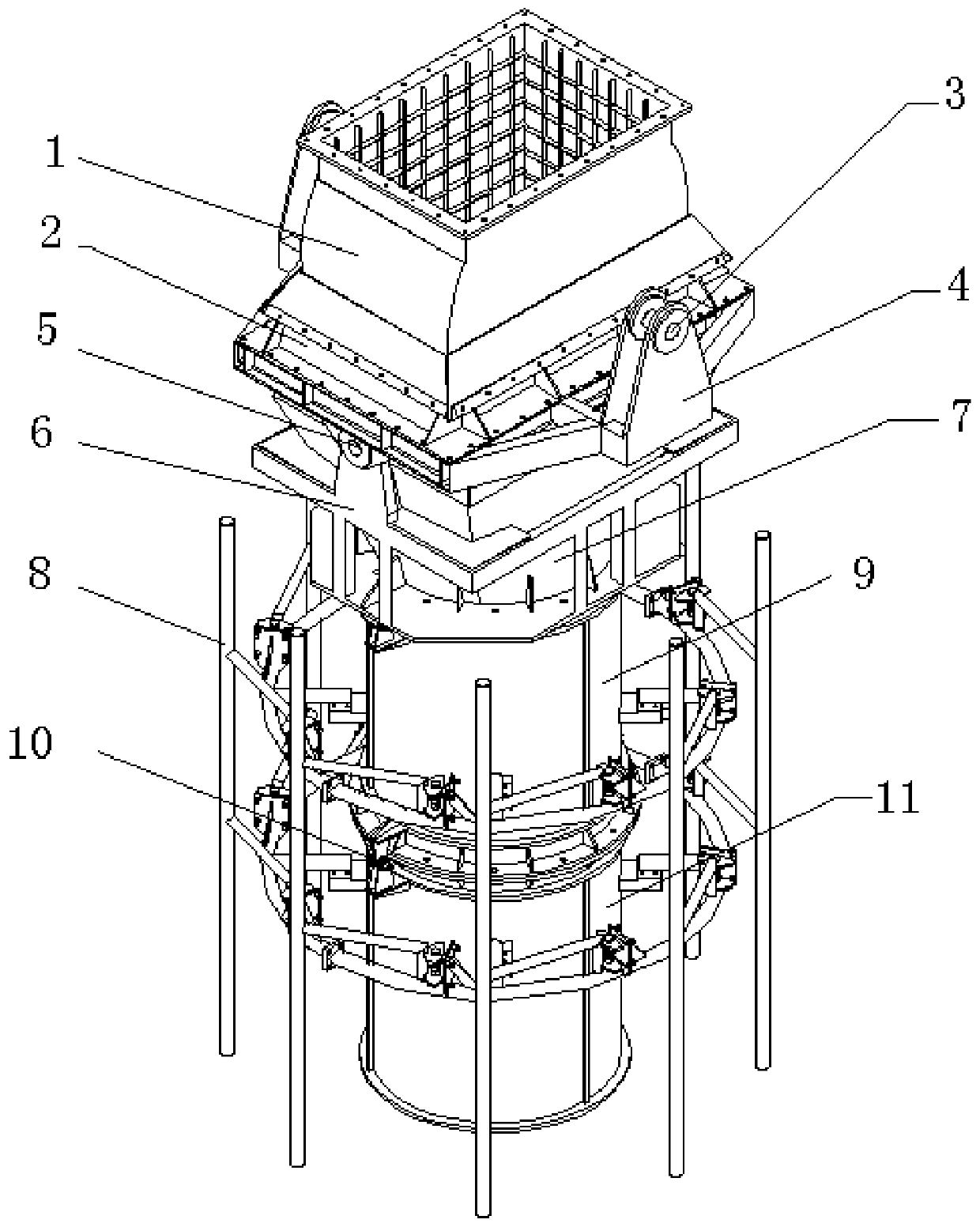
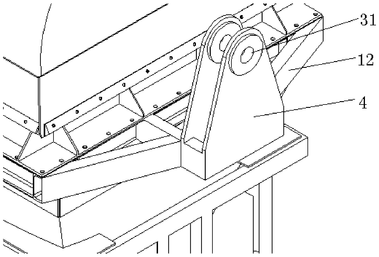
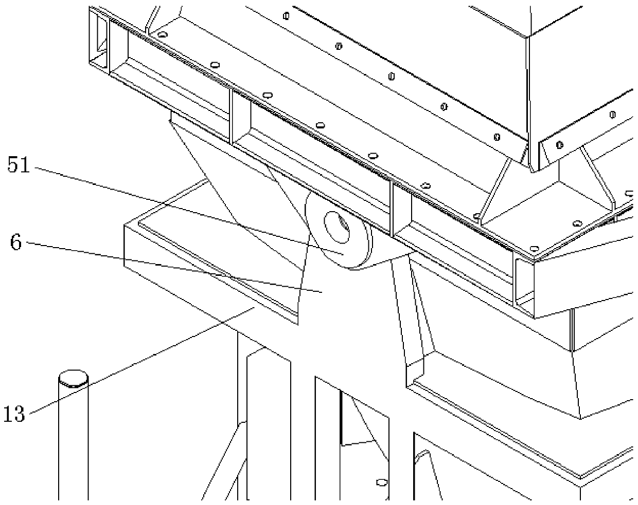
[0046] This embodiment provides a chute, such as figure 1 As shown, it includes a body, a first transition hopper 2 , a second transition hopper 7 , a first hinge 3 , and a second hinge 5 .

[0047] There is an anti-collision protection bar 8 outside the body. In this embodiment, the body includes the first chute section 9 and the second chute section 11 from top to bottom. The first chute section 9 and the second chute section 11 The connection is detachable. In other alternative embodiments, the number of chute sections is determined according to actual needs, and may include three chute sections or only one chute section. The anti-collision protection bar 8 includes a plurality of vertical bars arranged at intervals outside the body, each vertical bar is connected outside the body by a connecting rod, and a plurality of vertical pin shafts are arranged outside the body, and springs are connected on the pin shafts. When the anti-collision protection bar 8 hits an obstacle, ...


PUM


Abstract

The invention provides a slip cylinder. The slip cylinder comprises a body, a first transition hopper, a second transition hopper, a first hinge portion and a second hinge portion. Anti-collision protection rods are arranged outside the body. The first transition hopper is suitable for being detachably connected with a top transition hopper connected to a ship loader. The second transition hoppercommunicates with the first transition hopper and is arranged below the first transition hopper, and the second transition hopper is connected above the body. The first hinge portion is fixedly arranged outside the first transition hopper and suitable for being hinged to a cantilever of the ship loader. The second hinge portion is connected between the first transition hopper and the second transition hopper to enable the second transition hopper to be capable of swinging relative to the first transition hopper, and the swinging direction of the second transition hopper relative to the first transition hopper is parallel or coplanar to the walking direction of the ship loader. When the anti-collision protection rods collide with an obstacle, the second transition hopper drives the body toswing in the direction opposite to the walking direction of the ship loader, thus, rigid collisions of the slip cylinder and the obstacle are converted into flexible collisions, and the body can be prevented from being crashed.

Description

technical field [0001] The invention relates to the technical field of conveying equipment, in particular to a chute. Background technique [0002] In order to improve the loading efficiency of bulk materials, the ship loader, as a continuous transportation machine for bulk materials, has a wide range of requirements and scope of application. When the ship loader is running, due to the wind load, tide, and the rotation of the ship loader itself, the relative position between the chute and the ship will change all the time. In order for the chute of the ship loader to effectively drain water and prevent dust, it is necessary to allow the chute to enter the hatch. At the same time, in order to allow the materials to be evenly stacked at the bottom of the bilge, it is necessary to change the position of the discharge point from time to time. These make The chute is easy to collide with the ship. [0003] In the prior art, the chute is hung under the head of the inner wall fra...

Claims


Application Information

Patent Timeline
Patent Type & Authority Applications(China)
IPC IPC(8): B65G11/02B65G11/18
CPCB65G11/02B65G11/18
Inventor 黄振国叶阜李波张起伟周铁梁李玉民王华贵
Owner HUADIAN HEAVY IND CO LTD
Why Eureka
Try Eureka