Building shear wall formwork supporting system

A formwork support and shear wall technology, which is applied in construction, building structure, and on-site preparation of building components, etc., can solve problems affecting the quality of shear wall pouring, gaps in formwork joint positions, and inconvenient formwork joint positioning, etc. Achieve the effect of facilitating construction work, improving accuracy and improving construction efficiency

Active Publication Date: 2020-02-21
CHINA CONSTR SEVENTH ENG DIVISION CORP LTD
View PDF6 Cites 2 Cited by
  • Summary
  • Abstract
  • Description
  • Claims
  • Application Information

AI Technical Summary

Problems solved by technology

[0002] As the load-bearing wall in the building structure, the shear wall bears the vertical load from the horizontal components and also bears the horizontal load from the wind or earthquake. Before the concrete is poured, the shear wall needs to set up the formwork in advance. The existing The templates used in the technology include rectangular boards of various materials such as wood boards and aluminum boards. The formwork is fixed, and the support work of the formwork is relatively complicated and there is the problem of inconvenient positioning of the adjacent formwork, which may further cause a gap at the formwork joint position. During the pouring process, the formwork will bear the large lateral pressure of the concrete. If there is a gap, there will be a problem of grout leakage, which will affect the pouring quality of the shear wall

Method used


Image

  • Building shear wall formwork supporting system
  • Building shear wall formwork supporting system
  • Building shear wall formwork supporting system

Examples


specific Embodiment approach

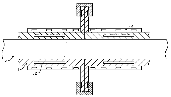
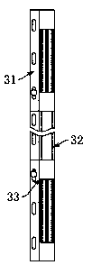
[0041] After the anchor bar of the shear wall is fixed, splicing formwork 1 is set up on both sides of the anchor bar, that is, on both sides of the precast wall a. First, the second connecting member 3 is placed on the ground, that is, according to the preset Lay the connecting rods on the ground, and adjust the length of the connecting rods to adapt to the length of the wall a. First, use anchor bolts to fix the ends of the connecting rods on the ground, and then adjust the first connecting rods 31 and the second connecting rods. The relative position of bar 32 makes each first connecting rod 31, the second connecting rod 32 expose the same length, and further use bolts to pass through the bolt holes of the first connecting rod 31, the second connecting rod 32 to the first connecting rod 31, The relative position of the second connecting rod 32 is fixed, and the adjacent connecting rods are connected by the connecting structure 4. The connection angle between the connecting s...


PUM


Abstract

The invention relates to a shear wall formwork supporting system, and particularly provides a building shear wall formwork supporting system. The building shear wall formwork supporting system comprises a plurality of splice formworks, connecting pieces extend from the left side and the right side of each splice formwork, the splice formworks which are transversely adjacent are connected through first connecting components, and the splice formworks are fixed to the ground through second connecting components. The splice formworks which are longitudinally adjacent are connected through positioning pieces, and the first connecting components are inserted into connecting grooves in connecting pieces adjacent to every two adjacent splice formworks. Each second connecting component comprises aplurality of connecting rods, each connecting rod is of a telescoping structure with the length capable of being adjusted, and a plurality of insertion pieces of an E-shaped structure are fixedly arranged on the connecting rods and correspond to the splice formworks. The building shear wall formwork supporting system is used for improving the building efficiency of the splice formworks of a shearwall, and gaps are prevented from being generated when the splice formworks are connected.

Description

technical field [0001] The invention relates to a splicing template support system for a building shear wall. Background technique [0002] As the load-bearing wall in the building structure, the shear wall bears the vertical load from the horizontal components and also bears the horizontal load from the wind or earthquake. Before the concrete is poured, the shear wall needs to set up the formwork in advance. The existing The templates used in the technology include rectangular boards of various materials such as wood boards and aluminum boards. The formwork is fixed, and the support work of the formwork is relatively complicated and there is the problem of inconvenient positioning of the adjacent formwork, which may further cause a gap at the formwork joint position. During the pouring process, the formwork will bear the large lateral pressure of the concrete. There is a problem of grout leakage in the gap, which affects the pouring quality of the shear wall. [0003] Com...

Claims


Application Information

Patent Timeline
Patent Type & Authority Applications(China)
IPC IPC(8): E04G17/14
CPCE04G17/14
Inventor 郑培君张中善陈璐
Owner CHINA CONSTR SEVENTH ENG DIVISION CORP LTD
Why Eureka
Try Eureka