Supercharge Your Innovation With Domain-Expert AI Agents!

Combined wheel and lighter using same

A combined wheel and lighter technology, which is applied in the direction of igniter with fuel, combustion ignition, combustion method, etc., can solve the problems of affecting the stability of use, loss of flaps to identify combined wheels, and reduced production efficiency, so as to reduce the rework of waste products Effects of workload, improvement of recognition accuracy, and improvement of assembly accuracy

Inactive Publication Date: 2020-02-21
漆仕勋
View PDF0 Cites 0 Cited by
  • Summary
  • Abstract
  • Description
  • Claims
  • Application Information

AI Technical Summary

Problems solved by technology

However, this structure has the following defects: 1. Due to the small diameter difference between the large shaft and the small shaft, the contour difference between the large shaft and the small shaft is also small. The groove cavity will be unable to identify and prevent the insertion of the large shaft due to wear, resulting in the loss of the function of the flap to distinguish the direction of the combined wheel, increasing the scrap rate and requiring rework; 2. Due to the small difference in the contour of the large shaft and the small shaft, Assemblers cannot observe the difference through direct vision, so that they cannot check and correct the combination wheel that has completed the embedding of the flap. They can only verify the judgment by observing whether it can be matched with the lighter and installed and generate sparks stably. Because it cannot be done in the early assembly process Verification of the accuracy of the installation posture of the combined wheel increases the difficulty of rework and disassembly, which not only reduces production efficiency, but also easily increases production costs and scrap rates due to component damage during disassembly and rework
[0005] In addition, when the diameters of the large shaft and the small shaft differ greatly, the diameter of the small shaft is smaller, which affects the structural strength of the small shaft, and is prone to breakage due to external force, affecting the stability of use.

Method used


Image

  • Combined wheel and lighter using same
  • Combined wheel and lighter using same
  • Combined wheel and lighter using same

Examples


Embodiment 1

[0031] This embodiment provides a combination wheel and a lighter using it.

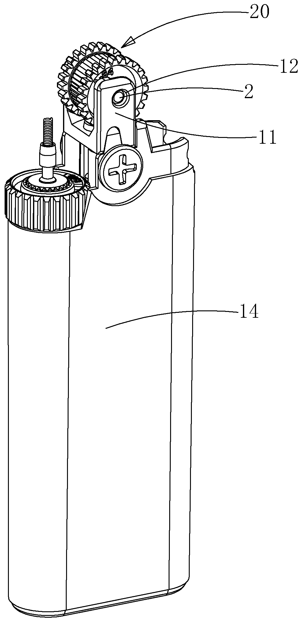
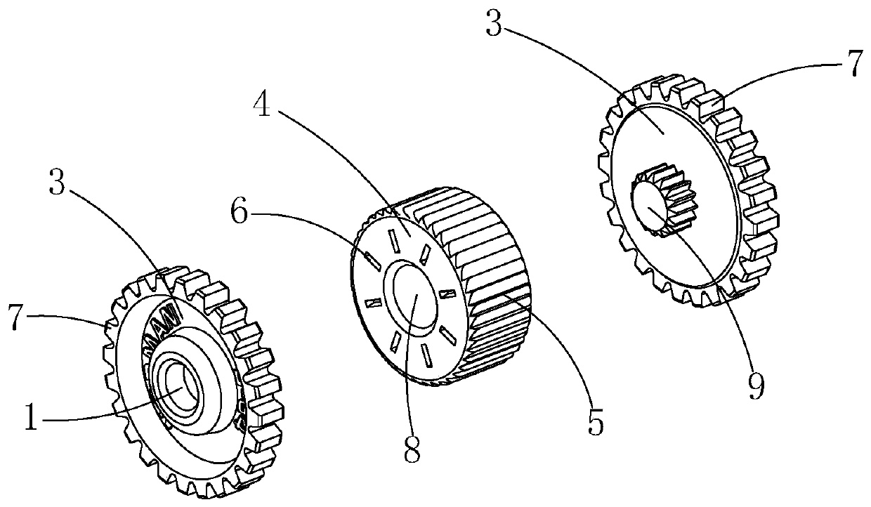
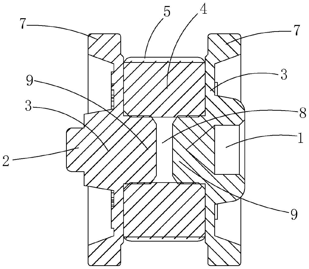
[0032] Such as figure 1 , 3 As shown in , 4, a lighter is composed of a casing, a combination wheel rotatably connected to the casing, and a flint 10 matched with the combination wheel. The casing is provided with a machine fork, and the machine fork includes Two oppositely arranged connectors 11, the opposite surfaces of the connectors 11 are respectively provided with an assembly hole 12 for the insertion and connection of the installation shaft 2 and an assembly shaft 13 for the sleeve connection of the installation hole 1. After the installation is in place, the combination The wheel is rotatably mounted on the fork, so that the knife edge 5 that rotates with the combined wheel scrapes and rubs against the flint 10 .

[0033] In this embodiment, a fuel chamber is provided in the casing, and an injection port is provided on the fuel chamber. The combination wheel rubs against the flint 10 to gen...

Embodiment 2

[0054] Compared with the first embodiment, this embodiment provides another lighter structure.

[0055] Such as Image 6 , 7 As shown, the casing is a split structure, including a body 14 and a machine fork 15, the top of the body 14 is provided with a socket 16, the bottom of the machine fork 15 is inserted into the socket 16, and the top forms a mechanism exposed to the socket 16. Fork, a fool-proof assembly is provided between the periphery of the hole 16 and the machine fork 15. After the combination wheel is installed in place, the knife edge 5 is set in a preset direction.

[0056] The top of the body 14 is provided with a socket 16 , and when installed, the bottom of the machine fork 15 is vertically inserted into the socket 16 so that the machine fork is exposed on the top of the body 14 . In order to prevent the machine fork 15 from being installed in reverse, the installation posture of the machine fork 15 is checked and corrected by setting the fool-proof componen...

Embodiment 3

[0063] Compared with the first embodiment, this embodiment provides another lighter structure.

[0064] In this embodiment, the casing is a split structure, including a body 14, a middle frame sleeved on the body 14, and a machine fork 15 arranged on the middle frame. The machine fork and the middle frame are of an integrated structure. During installation, the combination wheel is rotatably installed on the machine fork 15, and the machine fork 15 is assembled to the body 14 by the middle frame located below it, so that the combination wheel is affixed to the body 14 top.


PUM


Abstract

The invention relates to a combined wheel and a lighter using the same. A combined wheel of an existing lighter is prone to be assembled in the wrong direction. The combined wheel comprises a wheel body, wherein the middle parts of the two end surfaces of the wheel body are provided with a mounting hole and a mounting shaft correspondingly, the mounting hole and the mounting shaft are arranged along the axis of the wheel body, and the assembly direction of the combined wheel is identified by distinguishing the end surface outlines of the combined wheel. The mounting hole and the mounting shaftare arranged on the end surfaces of the two ends of the wheel body correspondingly, the cutter edge orientation, the reference object for judging the mounting direction of the combined wheel in the past, is replaced by the relative position relationship between the mounting hole and the mounting shaft, the identification accuracy is improved by increasing the difference of the outlines of the twoends of the wheel body, the assembly accuracy can be effectively improved, the production cost is reduced by reducing rework workload of waste products, and the assembly experience is improved.

Description

technical field [0001] The invention relates to the field of lighters, in particular to a combined wheel and a lighter using the same. Background technique [0002] Existing lighters include a casing with a fuel chamber inside and an ignition assembly for ignition. The ignition assembly can be electronic or grinding wheel ignition. The ignition assembly of the existing grinding wheel ignition method includes a rotatable combination wheel and a flint that cooperates with the combination wheel for friction and ignition. The combination wheel includes a steel wheel with a knife edge on the outer wall and side wheels coaxially arranged at both ends of the steel wheel. When in use, the user drives the steel wheel to rotate by turning the edge wheel, and the steel wheel scrapes the flint through the edge of the knife to generate sparks for ignition. [0003] During production, the steel wheel is cylindrical, and both ends of the steel wheel are flat surfaces. The steel wheel is p...

Claims


Application Information

Patent Timeline
IPC IPC(8): F23Q2/46F23Q2/38
CPCF23Q2/38F23Q2/46
Inventor 漆仕勋
Owner 漆仕勋
Features
  • R&D
  • Intellectual Property
  • Life Sciences
  • Materials
  • Tech Scout
  • Unparalleled Data Quality
  • Higher Quality Content
  • 60% Fewer Hallucinations
Learn More