
Relative pose and inertia estimation method for spatial complete non-cooperative target

A non-cooperative target, relative pose technology, applied in the field of relative pose and inertia estimation of completely non-cooperative targets in space, can solve the problems of navigation algorithm failure, inability to realize online calculation, and excessive calculation amount.

Active Publication Date: 2020-02-21
NORTHWESTERN POLYTECHNICAL UNIV
View PDF10 Cites 14 Cited by
  • Summary
  • Abstract
  • Description
  • Claims
  • Application Information

AI Technical Summary

Problems solved by technology

[0004] Compared with the cooperative targets in traditional rendezvous and docking missions, completely non-cooperative targets such as faulty satellites, failed spacecraft, and space debris lack cooperative information for navigation, such as measurement beacons, interactive communications, and model parameters, resulting in the traditional Navigation algorithm fails
Existing navigation algorithms applied to non-cooperative targets either rely on the model of the target, or the calculation is too large to realize online calculation
The above methods either rely on a priori known shape and geometric dimensions, or require a priori known position of feature points on the target and the moment of inertia of the target, or require a priori known CAD model of the target, these targets are strictly speaking not totally non-cooperative target
However, the SLAM method used to solve the center of mass position, linear velocity, relative attitude, relative angular velocity, and inertia parameters of space-rotating non-cooperative targets requires a large amount of calculation and takes a long time, so it can only be calculated offline.

Method used


Image

  • Relative pose and inertia estimation method for spatial complete non-cooperative target
  • Relative pose and inertia estimation method for spatial complete non-cooperative target
  • Relative pose and inertia estimation method for spatial complete non-cooperative target

Examples


Embodiment Construction

[0125] The present invention will be described in detail below in conjunction with the accompanying drawings and specific embodiments.

[0126] The invention discloses a method for estimating the relative pose and inertia of a completely non-cooperative target in space. The method includes the following steps:

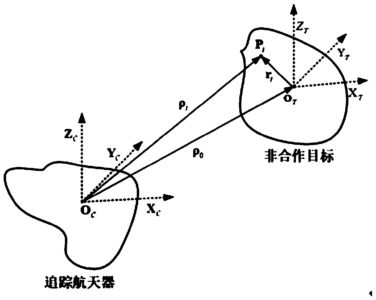
[0127] Step 1: Obtain the image information of the non-cooperative target in real time by two industrial cameras set on the tracking spacecraft at left and right intervals and with the same parameters, and obtain the image positions and image speeds of several feature points on the left and right cameras on the non-cooperative target through calculation , and then calculate the 3D position and velocity of each feature point in the camera coordinate system;

[0128]Step 2. According to the rigid body motion model, estimate the relative angular velocity of the non-cooperative target from the 3D positions and velocities of at least three feature points in step 1; combine ...


PUM


Abstract

The invention discloses a relative pose and inertia estimation method of a spatial complete non-cooperative target. The method comprises the steps that 1, two industrial computers which are arranged on a tracking spacecraft in a left-right spaced manner and are the same in parameters obtain image information of the non-cooperative target in real time, and 3D position and speed of each characteristic point in the camera coordinate system are calculated; 2, the relative angular velocity of the non-cooperative target is calculated from 3D positions and speeds of at least three characteristic points according to a rigid body motion model, and the relative pose of the non-cooperative target at random time is estimated; 3, the centroid position, the centroid speed and the relative positions of the characteristic points of the non-cooperative target are estimated according to the 3D positions and speeds as well as the relative pose and angular speed of the rigid body; and 4, a rotation inertia parameter of the non-cooperative target is estimated. Thus, the centroid position, the centroid speed, the relative pose, the relative angular speed and the inertial parameter of the complete non-cooperative target can be resolved needless of knowing the geometric shape and characteristic point positions of the complete non-cooperative target in advance.

Description

【Technical field】 [0001] The invention belongs to the technical field of navigation, and in particular relates to a method for estimating the relative pose and inertia of a completely non-cooperative target in space. 【Background technique】 [0002] In recent years, with the increasing frequency of human space activities, the number of space debris has risen sharply. As of January 2013, the large space debris (size not less than 10cm) cataloged by the Space Monitoring Network (SSN) under the US Strategic Command The number is close to 15,000, and the uncatalogued space debris smaller than 10cm (including small space debris smaller than 1mm and dangerous debris between large and small space debris) is even more difficult to estimate. The normal operation of space debris poses a serious threat, and it is urgent to carry out research on the removal of space debris. Compared with cooperative targets in traditional rendezvous and docking missions, non-cooperative targets such as ...

Claims


Application Information

Patent Timeline
IPC IPC(8): G01C21/16G01C21/24G01C11/00
CPCG01C11/00G01C21/165G01C21/24
Inventor 冯乾侯晓磊杨家男潘泉刘勇
Owner NORTHWESTERN POLYTECHNICAL UNIV
Learn More