Operation table for fiber splicing

An optical fiber fusion splicing and operating table technology, applied in the directions of light guide, optics, optical components, etc., can solve the problems of not easy to carry, the operation volume is too large, etc., and achieve the effect of easy portability, reduced space volume, and stable layout.

Pending Publication Date: 2020-02-21
BAICHENG POWER SUPPLY CO OF STATE GRID JILIN ELECTRIC POWER CO LTD
View PDF0 Cites 0 Cited by
  • Summary
  • Abstract
  • Description
  • Claims
  • Application Information

AI Technical Summary

Problems solved by technology

[0003] In view of this, the object of the present invention is to provide an operation table for optical fiber fusion splicing to solve the problems of the existing optical fiber fusion operation table, which are too bulky and difficult to carry.

Method used


Image

  • Operation table for fiber splicing
  • Operation table for fiber splicing
  • Operation table for fiber splicing

Examples


Embodiment Construction

[0024] The embodiment of the present invention discloses an operation table for optical fiber fusion splicing to solve the problems of the existing operation table for optical fiber fusion splicing, which are too bulky and difficult to carry.

[0025] The following will clearly and completely describe the technical solutions in the embodiments of the present invention with reference to the accompanying drawings in the embodiments of the present invention. Obviously, the described embodiments are only some of the embodiments of the present invention, not all of them. Based on the embodiments of the present invention, all other embodiments obtained by persons of ordinary skill in the art without making creative efforts belong to the protection scope of the present invention.

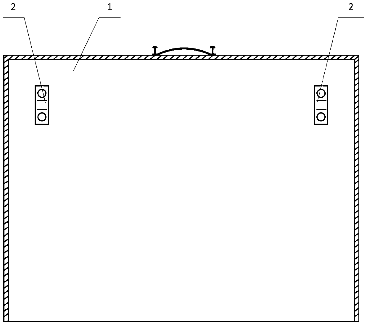
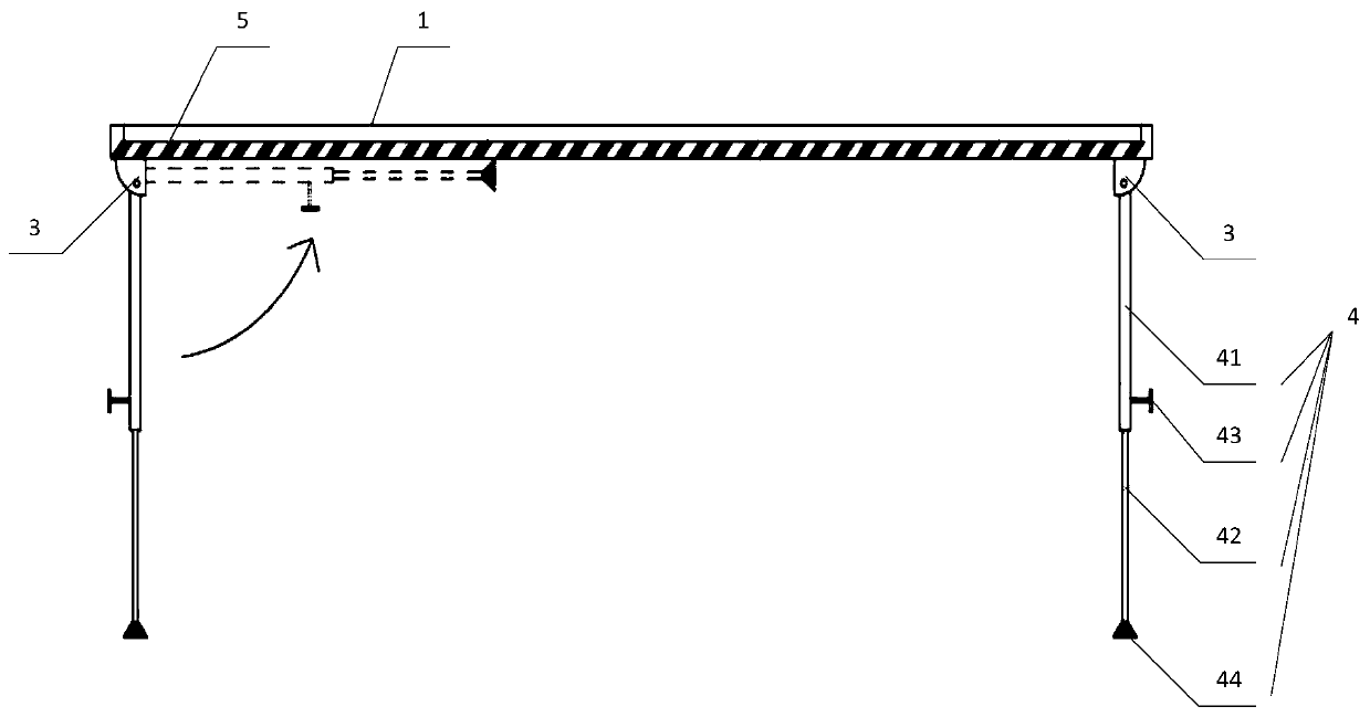
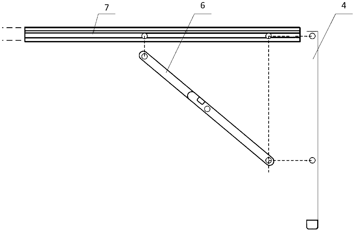
[0026] see Figure 1-Figure 3 , figure 1 It is a schematic top view structure diagram of an operation platform for optical fiber fusion splicing provided by the embodiment of the present invention; figu...


PUM


Abstract

The invention discloses an operation table for fiber splicing. The operation table comprises a table plate, wherein the table plate is used for forming a tabletop, a fixed fixture is arranged on the table plate and is used for fixing a fiber, multiple groups of support assemblies are uniformly arranged at the bottom of the table plate, can move along a vertical direction and are used for adjustinga distance between the table plate and ground, and the support assemblies are hinged with the table plate to collect and store the support assemblies. With the application of the operation table forfiber splicing, provided by the invention, a to-be-spliced fiber is fixed by the fixed fixture on the tabletop; meanwhile, the support assemblies are arranged at the bottom of the tabletop, height adjustment in the vertical direction can be performed according to different terrains so as to ensure stable arrangement of the table top; and the support assemblies are hinged with the table plate to achieve collection and storage, the space volume occupied by the operation table during transportation is reduced, and the operation table is convenient to carry.

Description

technical field [0001] The invention relates to the technical field of workbenches, and more specifically, to an operationbench for optical fiber fusion splicing. Background technique [0002] Power communication optical cable fault repair requires relatively short time. Optical cable fusion includes: making optical cable splice box, stripping cable, heat shrinkable tube, fiber core splicing, reeling, sealing box and other steps. After analysis and statistics, it is found that the main factors affecting the optical cable fusion time are: The reason is that the poor working environment and the unequal ground for emergency repairs lead to a low success rate of welding. After investigation, it was found that the operators mainly squatted on the ground or welded in the car, which affected work efficiency and quality. At present, the optical fiber fusion splicing consoles on the market are too bulky and heavy, and are not suitable for carrying in situations such as emergency repa...

Claims


Application Information

Patent Timeline
Patent Type & Authority Applications(China)
IPC IPC(8): G02B6/255
CPCG02B6/2556
Inventor 李雪侯钟宝于海广郭婧刘艳清李论王丽红张俊茹高科林耿云秀亢可
Owner BAICHENG POWER SUPPLY CO OF STATE GRID JILIN ELECTRIC POWER CO LTD
Why Eureka
Try Eureka