Potentiometer

A potentiometer and potential adjustment technology, which is applied in the field of potentiometers, can solve problems such as easy wear, decreased adjustment accuracy, and difficulty in realizing stepless adjustment, and achieves good stability, good adjustability, and long service life.

Pending Publication Date: 2020-02-21
张宇阳
View PDF0 Cites 0 Cited by
  • Summary
  • Abstract
  • Description
  • Claims
  • Application Information

AI Technical Summary

Problems solved by technology

In use, it is found that the spring is prone to wear during use, which reduces the adjustment accuracy and makes it difficult to achieve stepless adjustment, and the spring is prone to fatigue damage, which a

Method used


Image

  • Potentiometer
  • Potentiometer
  • Potentiometer

Examples


Embodiment 1

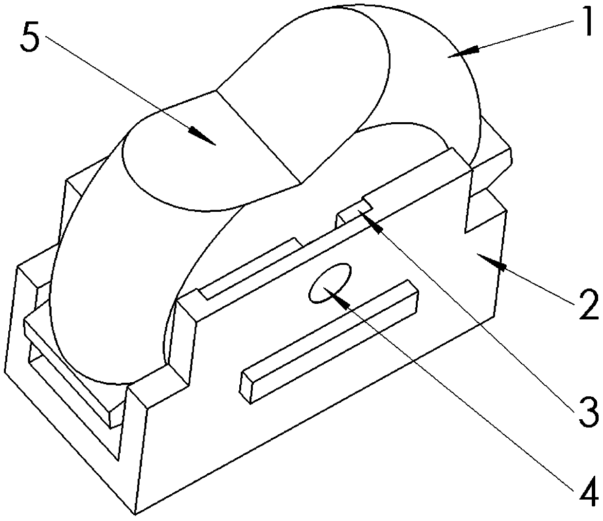
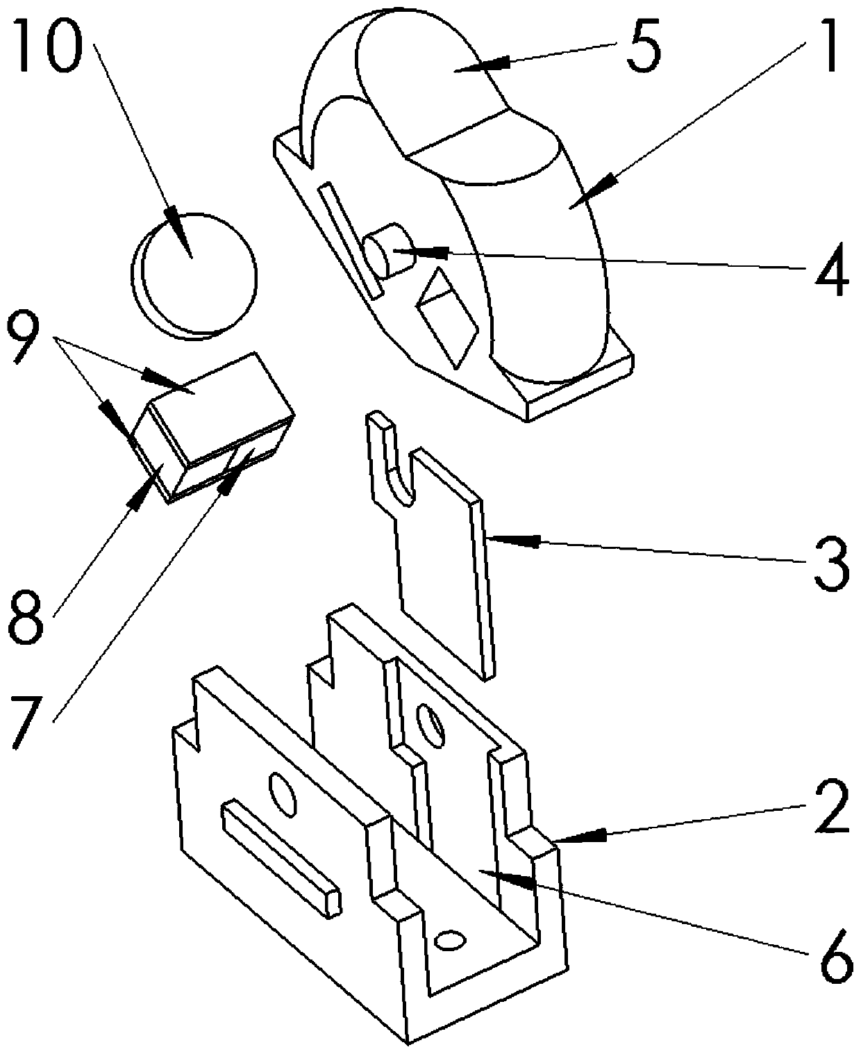
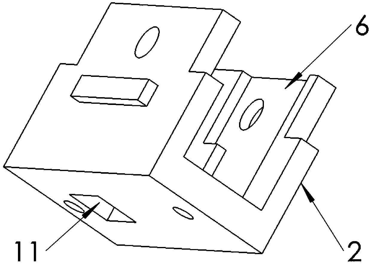
[0049] as attached figure 1 - attached image 3 As shown, the present invention provides a swing-type wear-resistant Hall potentiometer, including a movable block, a base block and a potential adjustment structure. The movable block is embedded on the base block, and a potential adjustment structure is provided on the movable block. Part of the potential adjustment structure is embedded with a magnetically conductive block structure, and the end of the magnetically conductive block structure protruding from the movable block is adsorbed with a magnetically conductive sheet, which is embedded and fastened on the base block, so that the magnetically conductive block structure and The magnetically-adsorbed magnetic sheets generate resistance to prevent the movable block from swinging relative to the base block.

[0050] The structure of the magnetically conductive block includes a non-magnetically conductive spacer made of plastic, a magnetic force generation block made of a mag...

Embodiment 2

[0056] as attached Figure 4 - attached Image 6 As shown, the present invention provides a push-pull wear-resistant Hall potentiometer, including a movable block, a base block and a potential adjustment structure. The movable block is embedded in the base block, and the potential adjustment structure is arranged on the movable block. Part of the potential adjustment structure is embedded with a magnetically conductive block structure, and the end of the magnetically conductive block structure protruding from the movable block is adsorbed with a magnetically conductive sheet, which is embedded and fastened on the base block, so that the magnetically conductive block structure and Magnetically adsorbing the magnetically conductive sheets together produces resistance that hinders the movement of the movable block relative to the base body block.

[0057] The magnetically conductive suction block structure includes a nonmagnetically conductive spacer made of plastic, a magnetic ...

Embodiment 3

[0062] as attached Figure 8 - attached Figure 10 As shown, the present invention provides a swing-type wear-resistant Hall potentiometer, including a movable block, a base block and a potential adjustment structure. The movable block is embedded on the base block, and the potential adjustment structure is provided on the movable block. The part away from the potential adjustment structure is embedded with a magnetically conductive block structure. The end of the magnetically conductive block structure protruding from the movable block is adsorbed with a magnetically conductive sheet. The magnetically conductive sheet is embedded and fastened on the base block, so that the magnetically conductive block structure It is magnetically adsorbed together with the magnetically conductive sheet to generate resistance that hinders the movement of the movable block relative to the base block.

[0063] The magnetically conductive suction block structure includes a nonmagnetically condu...


PUM


Abstract

The invention discloses a potentiometer that comprises a movable block, a base body block and a potential adjusting structure; the movable block is embedded into the base body block; the potential adjusting structure is arranged on the movable block; a magnetic conductive attraction block structure is embedded into the part, far away from the potential adjusting structure, of the movable block; magnetic conductive sheets are attracted at the end parts, extending out of the movable block, of the magnetic conductive attraction block structure; the magnetic conductive sheet is embedded and fastened on the base body block, the base body block is provided with a Hall element corresponding to the potential adjusting structure, the movable block can move relative to the base body block, the position relation between the potential adjusting structure and the Hall element is changed, and therefore the Hall element is affected by changes of a surrounding magnetic field to generate correspondingHall potential changes. The position relation between the potential adjusting structure on the base body block and the linear Hall element is changed, stepless or geared Hall potential adjustment is achieved, the adjustability is good, the magnetic conductive attraction block structure can be attracted to the magnetic conductive sheet together after being abraded, the service life is long, and stability is good.

Description

technical field [0001] The invention relates to the technical field of switch elements, in particular to a potentiometer. Background technique [0002] At present, quite a few Hall potentiometers, switches, etc. use the Hall effect, generally including Hall elements, permanent magnets and springs. The permanent magnets are close to the Hall elements to make the Hall potential of the Hall elements change, making the Hall effect The circuit connected with the Hall element will produce corresponding changes, such as the Chinese patent with the patent application number "2018214016136" and the patent name "A Safety Switch", including a base, a shaft, a spring, a magnetic element and a Hall element, the spring, The magnetic element and Hall element are located in the base, at least a part of the shaft can be located outside the base, and the rest of the shaft is located in the base, one end of the spring is in contact with the shaft, and the other end of the spring is in contact ...

Claims


Application Information

Patent Timeline
IPC IPC(8): H01C10/00
CPCH01C10/00
Inventor 张宇阳
Owner 张宇阳
Why Eureka
Try Eureka