Power electrical control cabinet convenient for wiring

A technology for electric power and control cabinets, which is applied in the direction of electrical components, substation/power distribution device casing, busbar/line layout, etc., which can solve the problems of inaccessible wires, skewed wiring, etc., and achieve the effect of increasing aesthetics

Inactive Publication Date: 2020-02-21
黎庆德
6 Cites 3 Cited by

AI-Extracted Technical Summary

Problems solved by technology

[0006] Aiming at the deficiencies of the prior art, the present invention provides a power and electrical control cabinet that is convenient ...

Method used

Wherein, in the placement box that control cabinet body 1 inwall bottom is fixedly installed, be placed with the standby movable block 19 that threaded rod 11 is fixedly installed, the size of standby movable block 19 is equal to movable block 12, and set up on standby movable block 19 The diameter of the wire inlet hole 13 is larger than the diameter of the wire inlet hole 13 opened on the upper surface of the movable block 12. If there are thicker wires that cannot be inserted into the wire groove or the wire harness needs to be separated from the two wire inlet grooves into the wire groove 7 , unscrew the movable block 12 and replace the spare movable block 19, so that thicker wires or wire harnesses can enter the wiring trough 7 with...

Abstract

The invention relates to the technical field of power electrical control cabinets, and discloses a power electrical control cabinet convenient for wiring, which comprises a control cabinet body and acabinet door formed on the control cabinet body; a component mounting frame is fixedly mounted on the front surface of the inner wall of the control cabinet body, and components are fixedly mounted onthe component mounting frame. The invention discloses the power electrical control cabinet convenient for wiring. A sliding groove, a round rod, a threaded rod and a movable block are arranged; in use, firstly, components are mounted on the component mounting frame according to specification requirements, and a safety gap between components is retained; if a wire inlet hole in the movable block and a wiring port of the component are not on the same straight line, the movable block is held by hand to rotate, so that the threaded rod is far away from the round rod, a sliding block can slide onthe round rod at the moment, so the wire inlet in the movable block can be aligned with the wiring port of the component; the movable block is rotated reversely to enable the threaded rod to abut against the round rod, the sliding block is fixed, wiring is vertical, and the attractiveness of wiring is improved.

Application Domain

Technology Topic

Image

  • Power electrical control cabinet convenient for wiring
  • Power electrical control cabinet convenient for wiring
  • Power electrical control cabinet convenient for wiring

Examples

  • Experimental program(1)

Example Embodiment

[0030] The technical solutions in the embodiments of the present invention will be clearly and completely described below in conjunction with the accompanying drawings in the embodiments of the present invention. Obviously, the described embodiments are only a part of the embodiments of the present invention, rather than all the embodiments. Based on the embodiments of the present invention, all other embodiments obtained by those of ordinary skill in the art without creative work shall fall within the protection scope of the present invention.
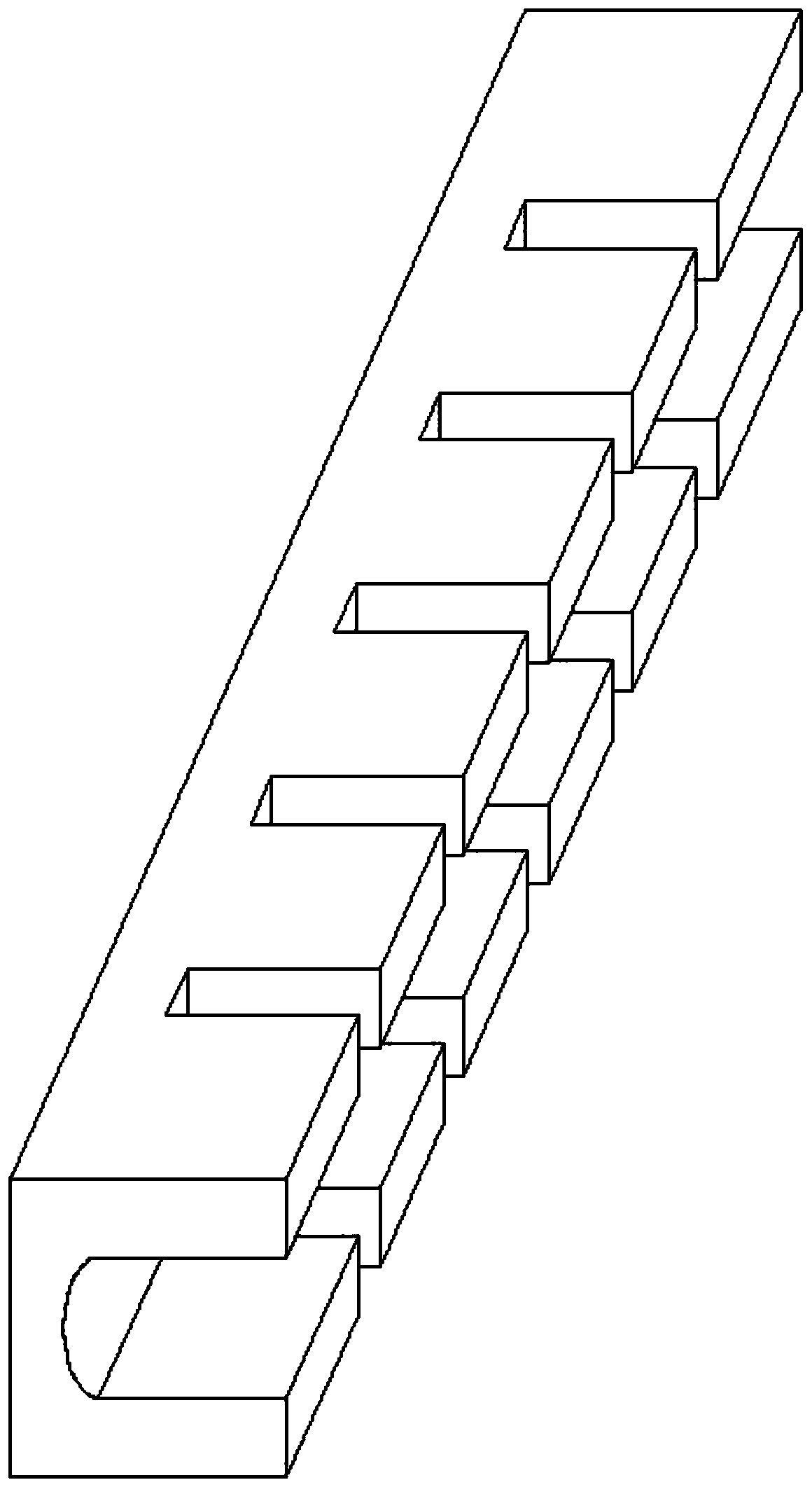
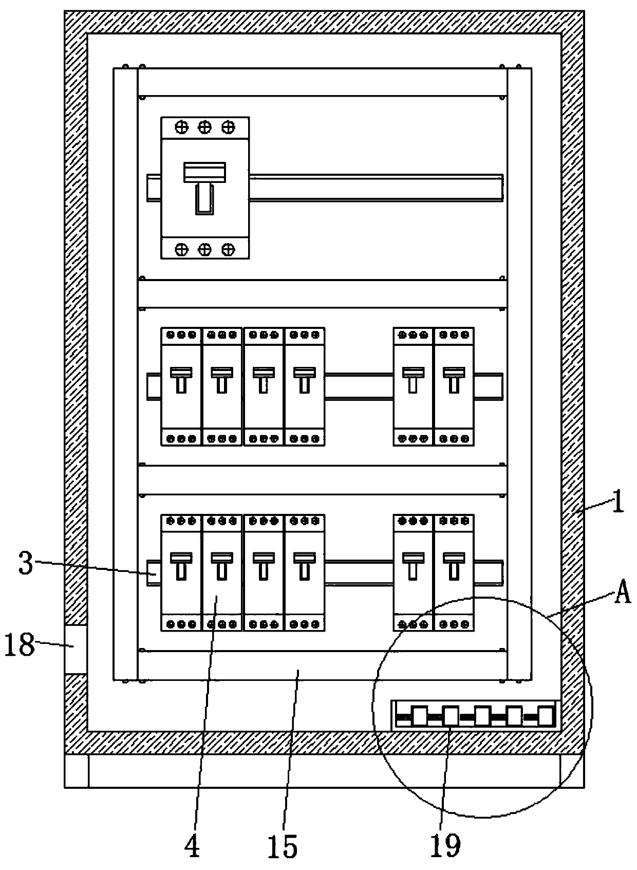
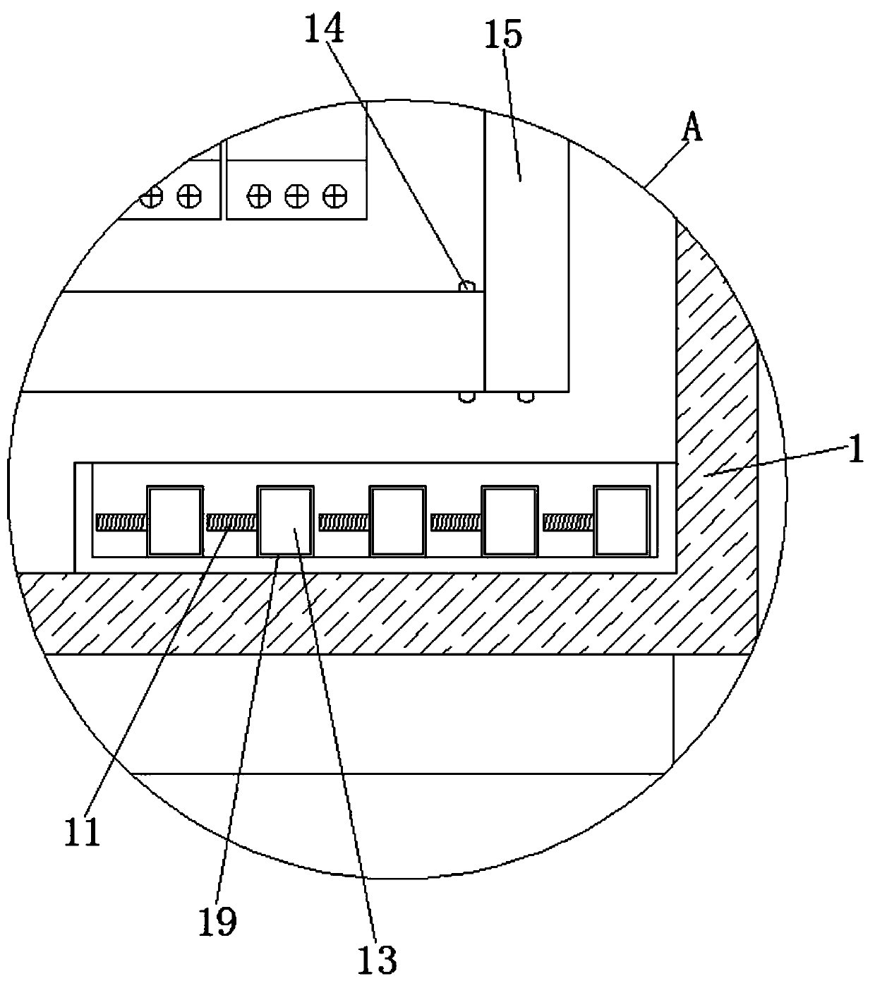
[0031] Such as Figure 1-9 As shown, the present invention provides a technical solution: a power and electrical control cabinet that is convenient for wiring, including a control cabinet body 1 and a cabinet door 2 provided therewith, a component mounting frame 3 is fixedly installed on the front of the inner wall of the control cabinet body 1, and The components 4 are fixedly installed on the component mounting frame 3, four horizontal wiring boards 5 and two longitudinal wiring boards 6 are fixedly installed on the front of the inner wall of the control cabinet body 1, and the horizontal wiring board 5 is connected to the longitudinal wiring board. The wiring board 6 is connected, the horizontal wiring board 5 and the longitudinal wiring board 6 are provided with wiring grooves 7 on the front, and the front of each horizontal wiring board 5 is provided with two sliding grooves 8 and the horizontal wiring board 5 The wiring groove 7 opened on the front is located between the two sliding grooves 8. A round rod 9 is fixedly installed on the inner wall of the sliding groove 8. The surface of the round rod 9 is slidingly sleeved with a slider 10, and the slider 10 is slidably mounted on Inside the chute 8, a threaded rod 11 is threaded in the threaded hole on the front of the slider 10. The back of the threaded rod 11 is in contact with the surface of the round rod 9, and the front of the threaded rod 11 is fixedly mounted with a movable block 12, the movable block 12 A wire inlet 13 is opened on the upper surface. The front surfaces of the horizontal wire board 5 and the longitudinal wire board 6 are covered with a cover plate 15 through elastic buckles 14, and the front surface of the movable block 12 is in contact with the back surface of the cover plate 15.
[0032] Wherein, both sides of the upper surface and lower surface of the horizontal wiring board 5 and the top and bottom of the longitudinal wiring board 6 are provided with bayonet ports 16, and the clamping block of the elastic buckle 14 is clamped inside the bayonet 16, using elasticity The buckle 14 and the bayonet 16 install the cover 15 on the horizontal wiring board 5 and the vertical wiring board 6. When wiring, remove the cover 15 for wiring. After the wiring is completed, cover the cover 15 , So that the block of the elastic buckle 14 is locked into the bayonet 16.
[0033] Among them, the number of sliders 10 slidably installed in each chute 8 is 8-12, and the distance between the two sliders 10 can be adjusted, and the distance between the two sliders 10 is adjusted according to the position of the component 4 Make adjustments. At the same time, compared with the traditional wiring rack, more gaps are reserved to dissipate the wires in the wiring trough 7. The outside air and the air in the wiring trough 7 can flow better, preventing the wiring trough 7 Heat buildup in internal wires.
[0034] Among them, the two sides of the longitudinal wiring board 6 are provided with circular holes 17 at equal distances, and the side of the control cabinet body 1 is provided with a wiring hole 18. The circular holes 17 are used to dissipate the wires in the longitudinal wiring board 6 and also Can be used as an outlet hole.
[0035] Among them, a spare movable block 19 fixedly installed with a threaded rod 11 is placed in a storage box fixedly installed at the bottom of the inner wall of the control cabinet body 1. The spare movable block 19 is the same size as the movable block 12, and an inlet line is provided on the spare movable block 19 The diameter of the hole 13 is larger than the diameter of the wire inlet 13 opened on the upper surface of the movable block 12. When a thicker wire cannot be inserted into the wire slot or the wire harness needs to be separated from the two wire inlets into the wire slot 7, the Unscrew the movable block 12 to replace the spare movable block 19, which can allow thicker wires or harnesses to enter the wiring trough 7, without the need to route the wires outside the wiring trough 7 or separately enter the wiring trough 7 from the two wiring troughs Inside, the operation is simple and convenient, and the wiring is neat and beautiful.
[0036] The length of the threaded rod 11 is greater than the length of the threaded hole on the front of the slider 10 by 1-2mm, and the threaded rod 11 fixedly installed on the spare movable block 19 and the threaded rod 11 fixedly installed on the movable block 12 have the same size, length and pitch. When the threaded rod 11 conflicts with the round rod 9, the slider 10 cannot move. If the length of the threaded rod 11 is less than the length of the threaded hole, the threaded rod 11 cannot conflict with the round rod 9 and cannot achieve a fixing effect. The threaded rod 11 fixedly installed on the movable block 19 and the threaded rod 11 fixedly installed on the movable block 12 are equal in size, length, and pitch. The movable block 12 can be lowered under the spare movable block 19, which can also achieve a fixed effect.
[0037] Among them, the two ends of the wiring groove 7 opened on the front of the horizontal wiring board 5 are connected to the two ends of the horizontal wiring board 5, the two ends of the sliding groove 8 are closed, and the horizontal wiring board 5 with opening at both ends is for connecting with the longitudinal wiring board. 6 is connected, the two ends of the sliding groove 8 are closed in order to install the round rod 9, so that the slider 10 slides on the round rod 9, and then the threaded rod 11 is used for fixing.
[0038] Working principle: When in use, first install the component 4 on the component mounting frame 3 according to the specifications, and leave a safety gap between the components 4. If the wire inlet 13 on the movable block 12 is not the same as the wiring port of the component 4 Directly, the hand-held movable block 12 rotates to make the threaded rod 11 far away from the round rod 9. At this time, the slider 10 can slide on the round rod 9 to align the wire inlet 13 on the movable block 12 with the wiring port of the component 4. Rotate the movable block 12 in the reverse direction to cause the threaded rod 11 to interfere with the round rod 9, and fix the slider 12 to make the wiring vertical and increase the aesthetics of the wiring. The movable block 12 can be rotated by holding the movable block 12 to make the threaded rod 11 separate from the slider 10 , Take the spare movable block 19 in the box placed at the bottom of the control cabinet body 1, screw the threaded rod 11 on the spare movable block 19 into the threaded hole on the front of the slider 10, due to the wire inlet hole on the spare movable block 19 The diameter of 13 is larger than the diameter of the wire inlet 13 opened on the upper surface of the movable block 12, which can allow thicker wires or wire bundles to enter the wire slot 7.
[0039] It should be noted that in this article, relational terms such as first and second are only used to distinguish one entity or operation from another entity or operation, and do not necessarily require or imply one of these entities or operations. There is any such actual relationship or order between. Moreover, the terms "include", "include" or any other variants thereof are intended to cover non-exclusive inclusion, so that a process, method, article or device including a series of elements not only includes those elements, but also includes those that are not explicitly listed Other elements of, or also include elements inherent to this process, method, article or equipment.
[0040] Although the embodiments of the present invention have been shown and described, those of ordinary skill in the art can understand that various changes, modifications, and substitutions can be made to these embodiments without departing from the principle and spirit of the present invention. And variations, the scope of the present invention is defined by the appended claims and their equivalents.

PUM

no PUM

Description & Claims & Application Information

We can also present the details of the Description, Claims and Application information to help users get a comprehensive understanding of the technical details of the patent, such as background art, summary of invention, brief description of drawings, description of embodiments, and other original content. On the other hand, users can also determine the specific scope of protection of the technology through the list of claims; as well as understand the changes in the life cycle of the technology with the presentation of the patent timeline. Login to view more.

Similar technology patents

Inorganic phosphorescent article and method for making same

InactiveUS20100285284A1Pronounced and sustained phosphorescent effectImprove aestheticsDecorative surface effectsDuplicating/marking methodsZinc sulfideEmergency light
Owner:LACOURSE BRIAN C

Surface treatment method of mirror stainless steel objects

InactiveCN102259287AImprove aestheticsAvoid the problem of overthrow deformation and sinkingPlane surface grinding machinesSurface grindingSandpaper
Owner:李俊霈

Classification and recommendation of technical efficacy words

Why Eureka
Try Eureka