
Water-cooled cable joint of induction furnace

A technology of water-cooled cables and induction furnaces, which is applied in the direction of cable joints, insulated cables, cables, etc., can solve the problems of customers' economic losses, increase in contact surface resistance, surface oxidation, etc., and achieve the effect of solving joint problems

Inactive Publication Date: 2020-02-21
HUAIBEI PINGXIANG ELECTRIC FURNACE
View PDF7 Cites 1 Cited by
  • Summary
  • Abstract
  • Description
  • Claims
  • Application Information

AI Technical Summary

Problems solved by technology

The analysis found that due to the structural design of the existing water-cooled cable head, it will generate heat when it is subjected to high-current operation, resulting in surface oxidation. Burn out the water-cooled cable head, bringing economic losses to customers

Method used


Image

  • Water-cooled cable joint of induction furnace

Examples


Embodiment 1

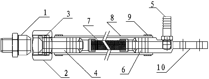
[0015] like figure 1 The shown water-cooled cable joint for an induction furnace includes an inductor end connector, a capacitor end connector, a cable core 7 connecting the inductor end connector and the capacitor end connector, and is sleeved on the inductor end connector and the capacitor end On the connector, the cable core 7 is placed in the water bushing 8, and the water channel is set in the sensor end connector and the capacitor end connector, and the water channel communicates with the water bushing 8 to form a waterway. Connect with cooling equipment to form circulating cooling.

[0016] In the prior art, the cable core passes through natural cooling with a current of 2.5-3A. When it is subjected to high current, it will generate heat and cause surface oxidation. Burn out the water-cooling cable head by igniting it. However, the structural design of the present invention allows the cable core to be cooled by water, and when the cable is cooled by water, it can carr...

Embodiment 2

[0018] As a specific structural design of Embodiment 1, the sensor end connector includes a water nut 1, a nut 2, a washer 3, and a sensor end connecting rod 4, and the sensor end connecting rod 4 includes a socket for connecting water. The rod body of the casing, the rod body is hollow for water passage, located at one end of the rod body, a cylindrical platform with an outer diameter larger than the outer diameter of the rod body, located at the other end of the rod body, a cable connector with an outer diameter smaller than the outer diameter of the rod body, 3 washers and 2 sets of nuts Connected to the sensor connecting rod 4, and the washer 3 is connected to the cylindrical platform, the nut 2 is sleeved outside the washer 3, one end of the water-through nut 1 is welded on the inductor, and the other end is matched and locked with the nut.

[0019] The cable connector of the connecting rod 4 at the sensor end is a hollow cylinder, one end of the cable core is inserted int...


PUM


Abstract

The invention discloses a water-cooled cable joint of an induction furnace. The water-cooled cable joint comprises an inductor end connector, a capacitor end connector, a cable core connected with theinductor end connector and the capacitor end connector, a water passing sleeve sleeving the inductor end connector and the capacitor end connector and used for putting a cable therein. A water path channels are respectively arranged in the inductor end connector and the capacitor end connector and communicate with the internal portion of the water passing sleeve to form a water path, and the water path is connected with a connection device to form circulating cooling. By the design of the water path and the structural design of the connectors, the real water passing cooling of the cable coreis achieved, the large current of 15-20A can be borne, and the connector problem of an existing induction melting furnace is thoroughly solved.

Description

technical field [0001] The invention relates to a water-cooled cable joint for an induction furnace, which belongs to the technical field of induction furnace equipment. Background technique [0002] For induction melting furnaces, when the inductor current is high, damage to the water-cooled cable head often occurs. The analysis found that due to the structural design of the existing water-cooled cable head, it will generate heat when it is subjected to high current operation, resulting in surface oxidation. As the oxidation intensifies, the resistance of the contact surface increases, causing the joint to overheat easily, so that it can catch fire Burning out the water-cooled cable head will bring economic losses to customers. Therefore, there is a need for a water-cooled cable joint that is reasonably designed and capable of withstanding large currents. Contents of the invention [0003] The purpose of the present invention is to solve the above-mentioned problems in ...

Claims


Application Information

Patent Timeline
Patent Type & Authority Applications(China)
IPC IPC(8): H02G15/18H02G3/03H01B7/42
CPCH01B7/423H02G3/03H02G15/18
Inventor 史万平
Owner HUAIBEI PINGXIANG ELECTRIC FURNACE
Learn More