Lighting device and linked lighting device

A technology for lighting devices and power supply devices, which is applied to the cooling/heating devices of lighting devices, lighting devices, components of lighting devices, etc., which can solve the problems of reduced energy conversion efficiency and shortened life of light-emitting elements, and achieve the purpose of suppressing height dimensions, Good effect on cooling performance

Pending Publication Date: 2020-02-21
MITSUBISHI ELECTRIC CORP +1
View PDF13 Cites 0 Cited by
  • Summary
  • Abstract
  • Description
  • Claims
  • Application Information

AI Technical Summary

Problems solved by technology

When the temperature of the light-emitting element increases due to the heat generation of the light-emitting element, the energy conversion efficiency will decrease, or the life of the light-emitting element will be shortened

Method used


Image

  • Lighting device and linked lighting device
  • Lighting device and linked lighting device
  • Lighting device and linked lighting device

Examples


Embodiment approach 1

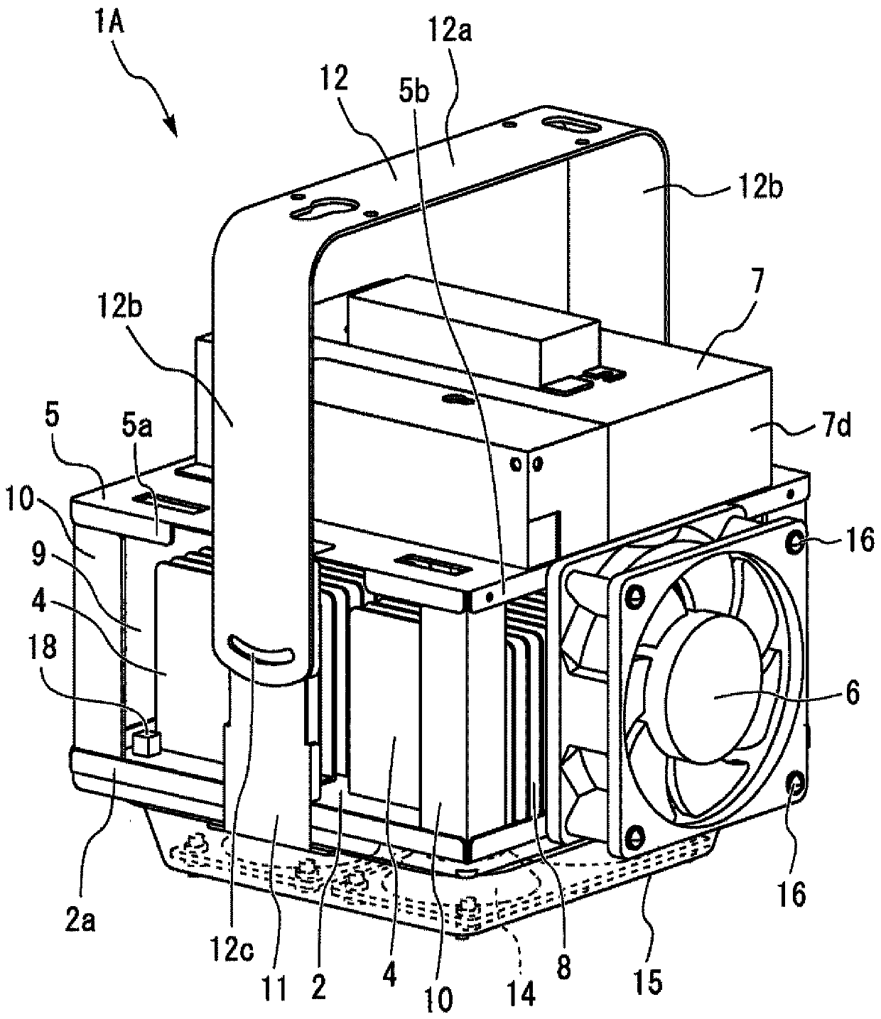
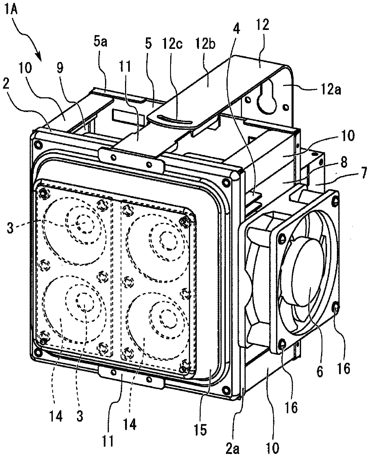
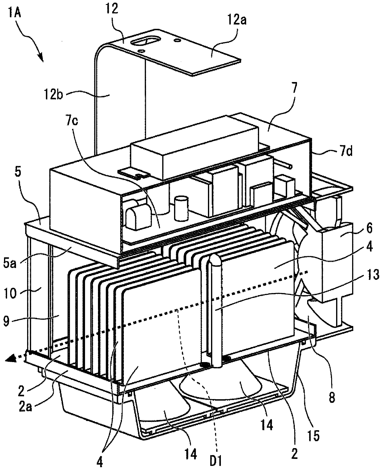
[0031] figure 1 It is a perspective view of the lighting device 1A according to Embodiment 1 viewed obliquely from above. figure 2 It is a perspective view of the lighting device 1A according to Embodiment 1 viewed obliquely from below. image 3 It is a cutaway perspective view of the lighting device 1A according to the first embodiment. Figure 4 It is a functional block diagram of the lighting device 1A according to the first embodiment. The lighting device 1A of Embodiment 1 shown in these figures is installed on the ceiling, and can be preferably used for illuminating the space below the lighting device 1A by irradiating light downward. In the following description, the up and down directions are determined based on the posture when the lighting device 1A is used. The lighting device 1A can be suitably used, for example, as a device that emits light beams of several thousand lumens to tens of thousands of lumens. The lighting device 1A is particularly suitable for ins...

Embodiment approach 2

[0078] Next, refer to Figure 6 Embodiment 2 will be described, focusing on differences from Embodiment 1 described above, and descriptions of the same parts or corresponding parts will be simplified or omitted. Figure 6 It is a perspective view of the lighting device 1B according to Embodiment 2 viewed obliquely from above.

[0079] Such as Figure 6 As shown, the cooling fan 6 included in the lighting device 1B of the second embodiment is provided at a slightly higher position than that of the first embodiment. The upper end of the cooling fan 6 is located higher than the second base 5 . The lower end of the cooling fan 6 is at a height between the first base 2 and the second base 5 . The cooling fan 6 is fixed to the power supply housing 7d with two screws 16 . The cooling fan 6 has a portion facing the power supply housing 7 d and a portion facing the first vent 8 .

[0080] Part of the airflow generated by the cooling fan 6 is in contact with the surface of the powe...

Embodiment approach 3

[0084] Next, refer to Figure 7 Embodiment 3 will be described with a focus on differences from Embodiment 1 described above, and descriptions of the same parts or corresponding parts will be simplified or omitted. Figure 7 It is a side view of the lighting device 1C according to the third embodiment.

[0085] Such as Figure 7 As shown, the illuminating device 1C according to the third embodiment differs from the first embodiment in that the center line AX of the cooling fan 6 is not inclined in parallel to the first base 2 . The center line AX is inclined so as to approach the first base 2 as it moves away from the cooling fan 6 .

[0086] A plurality of imaginary trajectories obtained by parallel moving a plurality of points in the area inside the air outlet of the cooling fan 6 toward the direction in which the airflow blows out from the air outlet of the cooling fan 6 includes the intersection with the first base 2. The trajectory L1 and the trajectory L2 passing thro...


PUM


Abstract

A lighting device (1A) is provided with: a light-emitting element disposed under a first base (2); a plurality of heat dissipation fins (4) disposed on the first base (2); a second base (5) disposed above the heat dissipation fins (4); a cooling fan (6); and a power supply device (7) having a power supply case (7d) which houses a light-source drive circuit for lighting the light-emitting element.The power supply device (7) is supported by the second base (5). A first vent (8) and a second vent (9) are formed between the first base (2) and the second base (5). The heat dissipation fins (4) arepositioned between the first vent (8) and the second vent (9). The cooling fan (6) is disposed so as to face the first vent (8). At least a part of the air stream generated by the cooling fan (6) passes through the first vent (8) and the second vent (9).

Description

technical field [0001] The present invention relates to a lighting device and a connected lighting device. Background technique [0002] Illuminating devices using light-emitting elements such as light-emitting diodes (LEDs) are widely used. When the temperature of the light-emitting element increases due to the heat generated by the light-emitting element, the energy conversion efficiency is lowered, or the life of the light-emitting element is shortened. Therefore, in order to prevent the temperature of the light-emitting element from increasing, it is desirable to ensure good heat dissipation for dissipating heat from the light-emitting element. In particular, since lighting devices for high ceilings installed on high ceilings of factories, warehouses, gymnasiums, and athletic facilities are placed in environments with high temperatures, cooling of light emitting elements becomes more important. [0003] The following Patent Document 1 discloses that an illuminating dev...

Claims


Application Information

Patent Timeline
Patent Type & Authority Applications(China)
IPC IPC(8): F21V29/503F21V23/00F21V29/508F21V29/67F21V29/76F21Y115/10
CPCF21V23/00F21V29/503F21V29/508F21V29/67F21V29/76
Inventor 伏江辽松原大介吉野勇人
Owner MITSUBISHI ELECTRIC CORP
Why Eureka
Try Eureka