A dust removal device for cutting new energy auto parts

A new energy vehicle, dust removal device technology, applied in the direction of combination device, separation method, dispersed particle separation, etc., can solve the problem of single exhaust device of dust removal device, dust cannot be conveniently and effectively processed, and it is difficult to control the range of dust removal, etc., to achieve improvement Functionality and the effect of improving convenience

Inactive Publication Date: 2021-06-18
东营瑞尔泰机电科技有限公司
View PDF5 Cites 0 Cited by
  • Summary
  • Abstract
  • Description
  • Claims
  • Application Information

AI Technical Summary

Problems solved by technology

[0003] In the production process of new energy auto parts, especially during grinding, a large amount of dust will be generated. In order to ensure the environment of processing and production and the normal operation of processing and production, it is necessary to carry out effective dust removal during processing such as grinding. A dust removal device will be used here. At present, the dust removal device used in the processing and production of new energy vehicles is a single exhaust device, which is difficult to control the range of dust removal. At the same time, the extracted dust cannot be conveniently and effectively processed. Therefore, it is necessary to design a new energy automobile spare parts cutting dust removal device to solve the above problems

Method used


Image

  • A dust removal device for cutting new energy auto parts
  • A dust removal device for cutting new energy auto parts
  • A dust removal device for cutting new energy auto parts

Examples


Embodiment 1

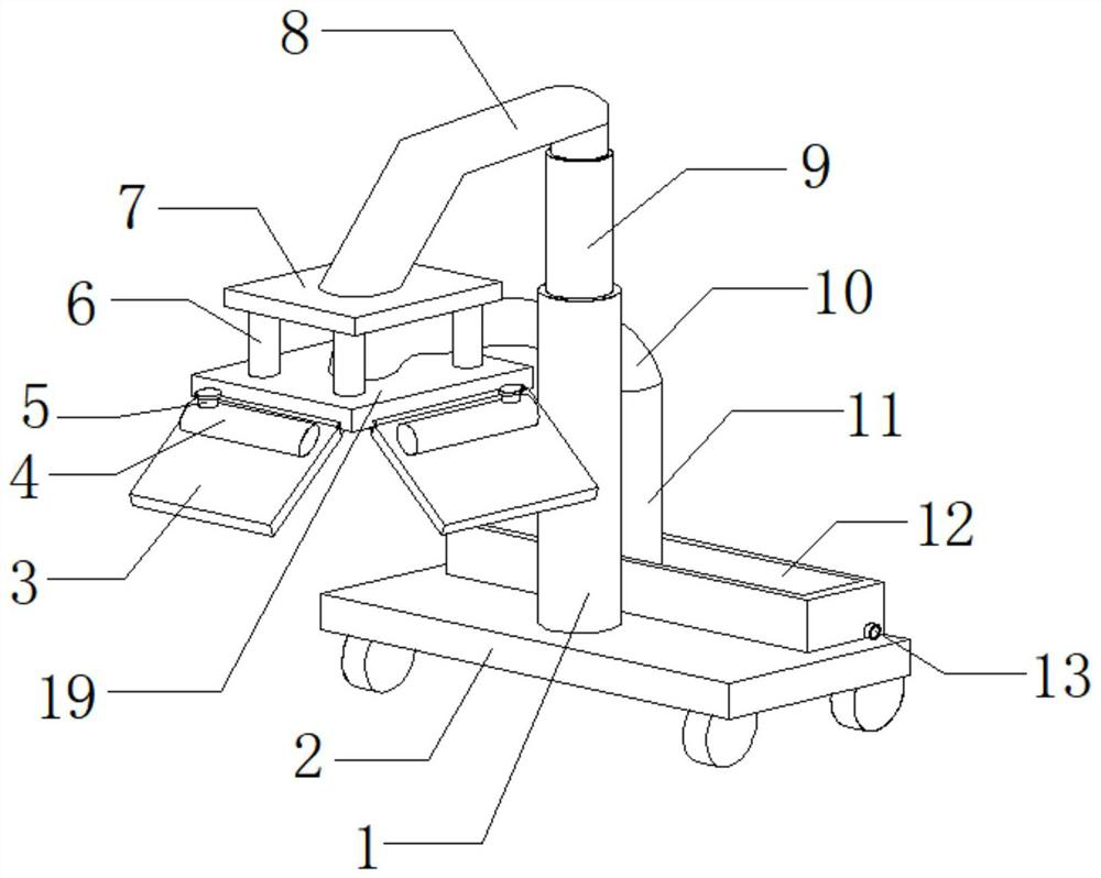
[0029] refer to Figure 1-3 , a dust removal device for cutting new energy automobile parts, including a support base plate 2 and a second support plate 19, the outer walls around the second support plate 19 are connected with a first support plate 3 through hinges, and four first support plates The top outer wall of the water storage pipe 4 is connected with the water storage pipe 4 by bolts, the bottom outer wall of the water storage pipe 4 is connected with the second aqueduct 20 by bolts, and the top side outer wall of the water storage pipe 4 is connected with the water inlet pipe 5 by bolts. And the top outer wall of the circumference of the water inlet pipe 5 is threadedly connected with the water inlet pipe cover, the bottom outer walls of the four first support plates 3 are provided with first grooves, and the top inner walls of the first grooves are all connected with cloth pads by bolts. 21. The inner walls on both sides of the four first grooves are connected with ...

Embodiment 2

[0034] refer to Figure 1-4 , a dust removal device for cutting new energy automobile parts, further comprising a mounting groove opened on the outer wall on the other side of the bottom of the support base plate 2, and the inner wall of the mounting groove is connected with a counterweight 25 by bolts.

[0035] When in use, the counterweight 25 can effectively balance the force on the other side of the device, improve the stability of the device in use, and prevent the device from toppling over.


PUM


Abstract

The invention belongs to the technical field of new energy vehicles, in particular to a dust removal device for cutting parts of new energy vehicles. Aiming at the problem that the dust removal range of the existing dust removal device is difficult to control, the following proposal is proposed, including the support base plate and the second support plate , the outer walls around the second support plate are connected with the first support plate through hinges, and the top outer walls of the four first support plates are all fixedly installed with water storage pipes, and the bottom outer walls of the water storage pipes are all fixedly installed with second As for the water guide pipe, a water inlet pipe is fixedly installed on the outer wall of the top side of the water storage pipe. In the present invention, the dust removal device for cutting new energy automobile spare parts can drive the first support plate to rotate by setting the second electric telescopic rod between the first support plate and the second support plate. , and then can conveniently change the degree of opening and closing of the four first support plates, thereby conveniently realizing dust removal in different ranges, and improving the convenience and functionality of the device.

Description

technical field [0001] The invention relates to the technical field of new energy vehicles, in particular to a dust removal device for cutting parts of new energy vehicles. Background technique [0002] New energy vehicles refer to the use of unconventional vehicle fuels as power sources (or the use of conventional vehicle fuels and new vehicle power devices), and the comprehensive vehicle power control and advanced technology in driving, the formation of advanced technical principles, with Automobiles with new technology and new structure. [0003] In the production process of new energy auto parts, especially during grinding, a large amount of dust will be generated. In order to ensure the environment of processing and production and the normal operation of processing and production, it is necessary to carry out effective dust removal during processing such as grinding. A dust removal device will be used here. At present, the dust removal device used in the processing and...

Claims


Application Information

Patent Timeline
Patent Type & Authority Patents(China)
IPC IPC(8): B01D50/00
CPCB01D50/60
Inventor 杨又伦曹剑覃远福刘建华
Owner 东营瑞尔泰机电科技有限公司
Why Eureka
Try Eureka