Spraying equipment

A technology of spraying equipment and spraying devices, applied in spraying devices, liquid spraying devices, etc., can solve the problems of reducing construction efficiency, inability to work in multiple directions, increasing construction complexity, etc., and achieve the effect of reducing construction complexity and improving construction efficiency

Inactive Publication Date: 2020-02-25
湖南易兴建筑有限公司
View PDF7 Cites 0 Cited by
  • Summary
  • Abstract
  • Description
  • Claims
  • Application Information

AI Technical Summary

Problems solved by technology

At present, the spraying equipment used in spraying operations, such as paint sprayers, is generally a single-tube one-way sprayer, which cannot work in multiple directions. During the spraying process, it is necessary to frequently pause and manually change the position and direction of the spray pipe or nozzle, which increases the construction cost. Complexity reduces construction efficiency

Method used


Image

  • Spraying equipment
  • Spraying equipment

Examples


preparation example Construction

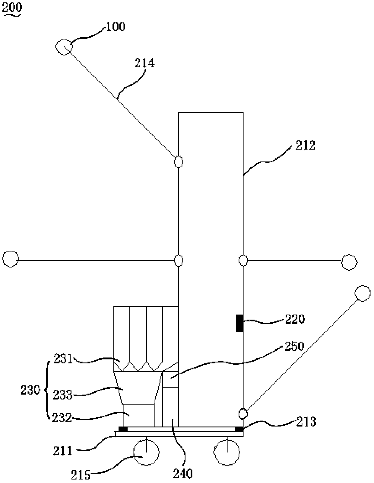
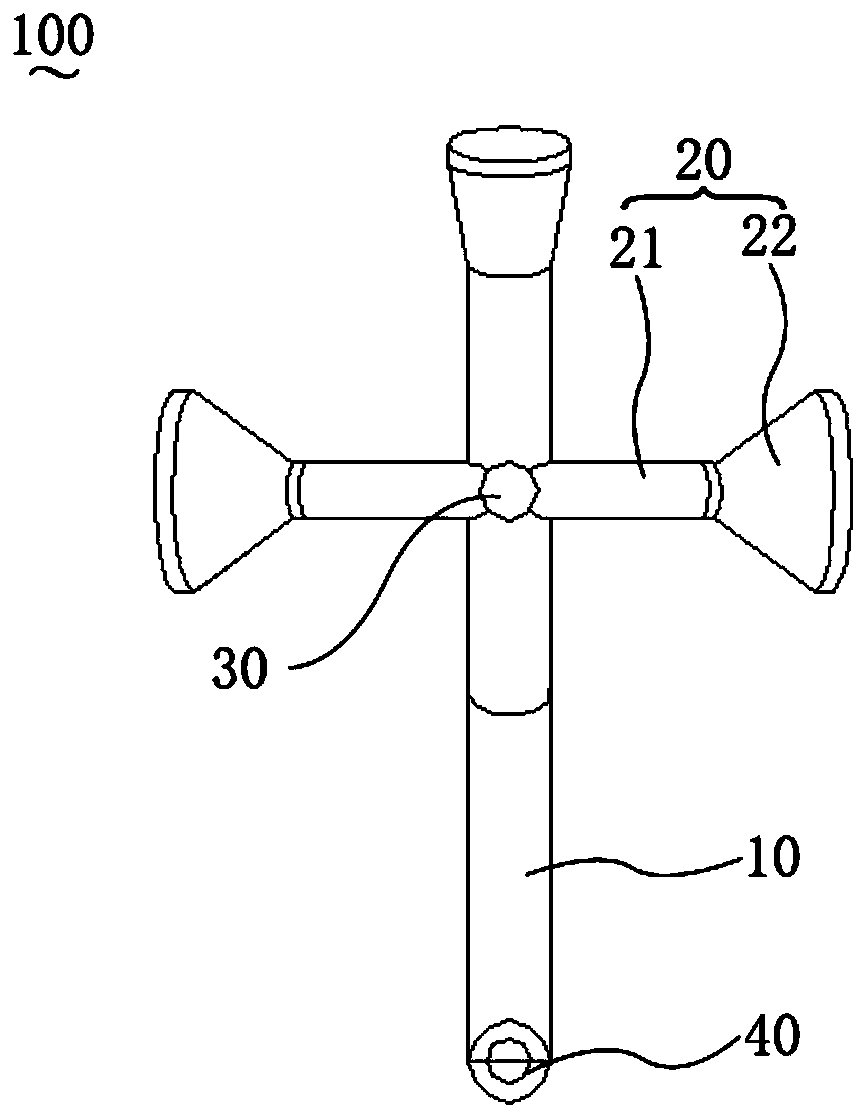
[0043] In a specific example, the preparation method of the universal spraying device 100 includes the following steps S1-S5:

[0044] S1. Take a nano-alloy tube as a paint delivery tube.

[0045] S2. Take a nano-alloy plate, cut it into multiple trapezoidal alloy plates, respectively curl the multiple trapezoidal alloy plates and connect the two waists of the trapezoid to obtain multiple frustoconical rolls.

[0046] S3. Taking a plurality of nano-alloy tubes and connecting one end with a plurality of truncated cone-shaped drums respectively to obtain a plurality of nozzles.

[0047] S4. Take a multi-directional control valve, and connect multiple nozzles with multiple output ports of the multi-directional control valve.

[0048] S5. Connect one end of the paint delivery pipe to the input port of the multi-directional control valve, and the other end to the rotary joint to obtain a universal spraying device.

Embodiment 1

[0051] A nano-alloy tube with a length of 1800mm, a wall thickness of 2mm, and an inner diameter of 15mm is selected as the paint delivery tube, and both ends of the tube are treated with internal wires so as to be inserted and tightened with other components.

[0052] Select a nano-alloy plate (thickness 2mm, length 500mm, width 50mm), first use a laser cutter to continuously cut the nano-alloy plate along the long side of the plate into 4 trapezoidal alloy plates (the length of the upper base is 31.4mm, and the length of the lower base is 157mm , height 40mm), and then use laser cladding to process the remaining triangular sheet material and small trapezoidal alloy plate into a trapezoidal alloy plate with the same size as the above four trapezoidal alloy plates (to ensure that the connection is smooth and compact).

[0053] The trapezoidal alloy plate (the length of the upper base is 31.4mm, the length of the lower base is 157mm, and the height is 40mm) is rolled into a frus...


PUM

PropertyMeasurementUnit
lengthaaaaaaaaaa
lengthaaaaaaaaaa
thicknessaaaaaaaaaa

Abstract

The invention relates to spraying equipment. The spraying equipment comprises a rack, a scanning device, a feeding device, a universal spraying device and a control device, wherein the rack comprisesa base and a supporting frame arranged on the base, and the supporting frame can move horizontally and vertically relative to the base; the scanning device is arranged on the supporting frame and usedfor scanning contour information of a surface to be sprayed; the feeding device is arranged on the base and used for feeding a coating; the universal spraying device comprises a coating delivery pipe, a plurality of spray nozzles, a multi-way control valve and a rotary joint; the multi-way control valve is provided with an input port and a plurality of output ports; one end of the coating delivery pipe communicates with an input port of the multi-way control valve, and the other end of the coating delivery pipe communicates with the rotary joint; the rotary joint communicates with the feedingdevice and can rotate by 360 degrees; and the plurality of spray nozzles communicate with output ports of the multi-way control valve correspondingly, and the coating delivery pipe is mounted on thesupporting frame. The spraying equipment provided by the invention can conveniently and automatically regulate and control the spraying direction and location in the spraying process, regulate the different spray nozzles to conduct spraying and regulate the spraying quantity to achieve multi-directional operation.

Description

technical field [0001] The invention relates to the technical field of construction machinery, in particular to a spraying equipment. Background technique [0002] In the construction industry, it is often necessary to spray the target object. For example, decorative boards, decorative strips, walls, etc., in order to improve their performance and appearance, it is generally necessary to spray a layer of media on their outer surfaces, such as protective paint, protective film and toning film. At present, the spraying equipment used in spraying operations, such as paint sprayers, is generally a single-tube one-way sprayer, which cannot work in multiple directions. During the spraying process, it is necessary to frequently pause and manually change the position and direction of the spray pipe or nozzle, which increases the construction cost. Complexity reduces construction efficiency. Contents of the invention [0003] Based on this, it is necessary to provide a spraying e...

Claims


Application Information

Patent Timeline
Patent Type & Authority Applications(China)
IPC IPC(8): B05B9/04B05B13/04B05B15/68B05B13/02B23P15/00
CPCB05B9/0403B05B13/0431B05B15/68B05B13/0278B23P15/00
Inventor 尹芬芳
Owner 湖南易兴建筑有限公司
Why Eureka
Try Eureka