Smart arterial compression device

A pressure device and arterial technology, applied in the field of medical equipment, can solve problems such as easy danger, unfavorable medical personnel to monitor patients in real time, long compression time, etc., and achieve the effects of time reporting and early warning, remote monitoring, and compact equipment

Inactive Publication Date: 2017-09-19
程孝惠
View PDF1 Cites 0 Cited by
  • Summary
  • Abstract
  • Description
  • Claims
  • Application Information

AI Technical Summary

Problems solved by technology

[0002] The current arterial compression devices are mainly manual. However, depending on the experience of the operator and the condition of the patient, it is easy to cause bleeding, oozing, redness and swelling due to insufficient compression, or ischemic symptoms caused by excessive compression. , Compression of local skin necrosis and other issues
In addition, due to the differences in physique, blood pressure, compression diameter, etc. of each patient, if the same pressure is always used for compression to stop bleeding, it is prone to danger, such as excessive compression force or excessive compression time, which may lead to irreversible tissue compression damage
The traditional arterial compression device is fixed, and the compression can only be adjusted and checked at the compression device, which is not conducive to real-time monitoring of the patient's condition by medical staff, nor is it conducive to remote control of the compression device by medical staff
In addition, the compression time of the arterial compression device is generally longer, up to 24 hours, and the compression force will decrease with the prolongation of the compression time, so the compression force needs to be readjusted after a period of time, which also increases the operating costs for the operator. workload

Method used


Image

  • Smart arterial compression device
  • Smart arterial compression device

Examples


Embodiment Construction

[0015] The present invention will be described in further detail below with reference to the accompanying drawings and specific embodiments.

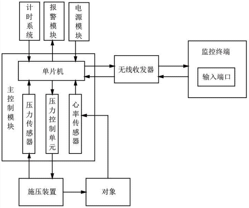
[0016] see figure 1 This is a system block diagram of an intelligent arterial compression device according to an embodiment of the present invention. An intelligent compression device includes a compression device, a main control module, a wireless transceiver and a monitoring terminal. The pressing device may be a balloon type or a spinning type pressing device. The main control module includes a pressure sensor, a heart rate sensor, a single chip microcomputer and a pressure control unit, wherein the pressure sensor, the heart rate sensor and the pressure control unit are respectively connected with the single chip computer. The pressure sensor can be installed between the pressure application device and the compression point of the object, and the pressure sensor is used to collect the current pressure signal of the pressure applic...


PUM


Abstract

The invention provides a smart artery compression device which comprises a pressure applying device, a master control module, a wireless transceiver and a monitoring terminal. The master control module comprises a pressure sensor, a heart rate sensor, a single chip microcomputer and a pressure control unit, wherein the pressure sensor, the heart rate sensor and the pressure control unit are connected with the single chip microcomputer respectively, the pressure sensor is used to collect current pressure signals of the pressure applying device, the heart rate sensor is used to collect pulse signals at the far end of a pressed area, and the pressure control unit is used to control the pressure applying device. The wireless transceiver is used to transmit signals and display the signals on the monitoring terminal. An input port is formed in the monitoring terminal and can send an input instruction to control the pressing device to work. The smart artery compression device further comprises a timing system, an alarm module and a power supply module which are connected with the single chip microcomputer respectively. The smart artery compression device can adjust the pressing force intelligently and remotely monitor the pressing condition in real time, and is convenient to use.

Description

technical field [0001] The invention relates to medical instruments, in particular to an intelligent arterial compression device. Background technique [0002] The current arterial compression devices are mainly manual. However, due to the experience of the operator and the condition of the patient, it is easy to cause bleeding, oozing and swelling due to insufficient compression force, or ischemia symptoms due to excessive compression force. , compression of local skin necrosis and other problems. In addition, due to the difference of each patient's physique, blood pressure, compression circumference, etc., if the same pressure is used all the time for compression and hemostasis, it is prone to danger, such as too high compression force or too long compression time, resulting in irreversible compression of the tissue. damage. The traditional arterial compression device is fixed, and the compression can only be adjusted and checked at the compression device, which is not c...

Claims


Application Information

Patent Timeline
Patent Type & Authority Patents(China)
IPC IPC(8): A61B17/12
CPCA61B17/12A61B2017/00017A61B2017/00119A61B2017/12004
Inventor 程孝惠孙文业邢春根余向前
Owner 程孝惠
Why Eureka
Try Eureka