
Crossed roller bearing and speed reducer

A cross-roller and reducer technology, applied in the field of bearings, can solve the problems that the inner ring cannot be processed with continuous tooth shape, the NN type reducer cannot be used, and the continuous tooth shape cannot be processed, and achieves compact structure, cost saving, The effect of reducing the axial installation space

Pending Publication Date: 2020-02-25
QUANTA MACHINERY CO LTD +1
View PDF1 Cites 1 Cited by
  • Summary
  • Abstract
  • Description
  • Claims
  • Application Information

AI Technical Summary

Problems solved by technology

[0003] The Chinese invention patent No. CN207437721U discloses a cross needle roller bearing with internal teeth. There are internal teeth that can perfectly match the flex spline of the harmonic reducer to reduce the axial size and meet the requirements of the harmonic reducer for robots; however, the inner teeth of the cross needle roller bearing There is a valve on the inner ring, so that the inner ring is not a complete circle, and the continuous tooth shape cannot be processed on the inner ring. Needle bearings cannot be used for NGWN and NN reducers

Method used


Image

  • Crossed roller bearing and speed reducer
  • Crossed roller bearing and speed reducer
  • Crossed roller bearing and speed reducer

Examples


Embodiment Construction

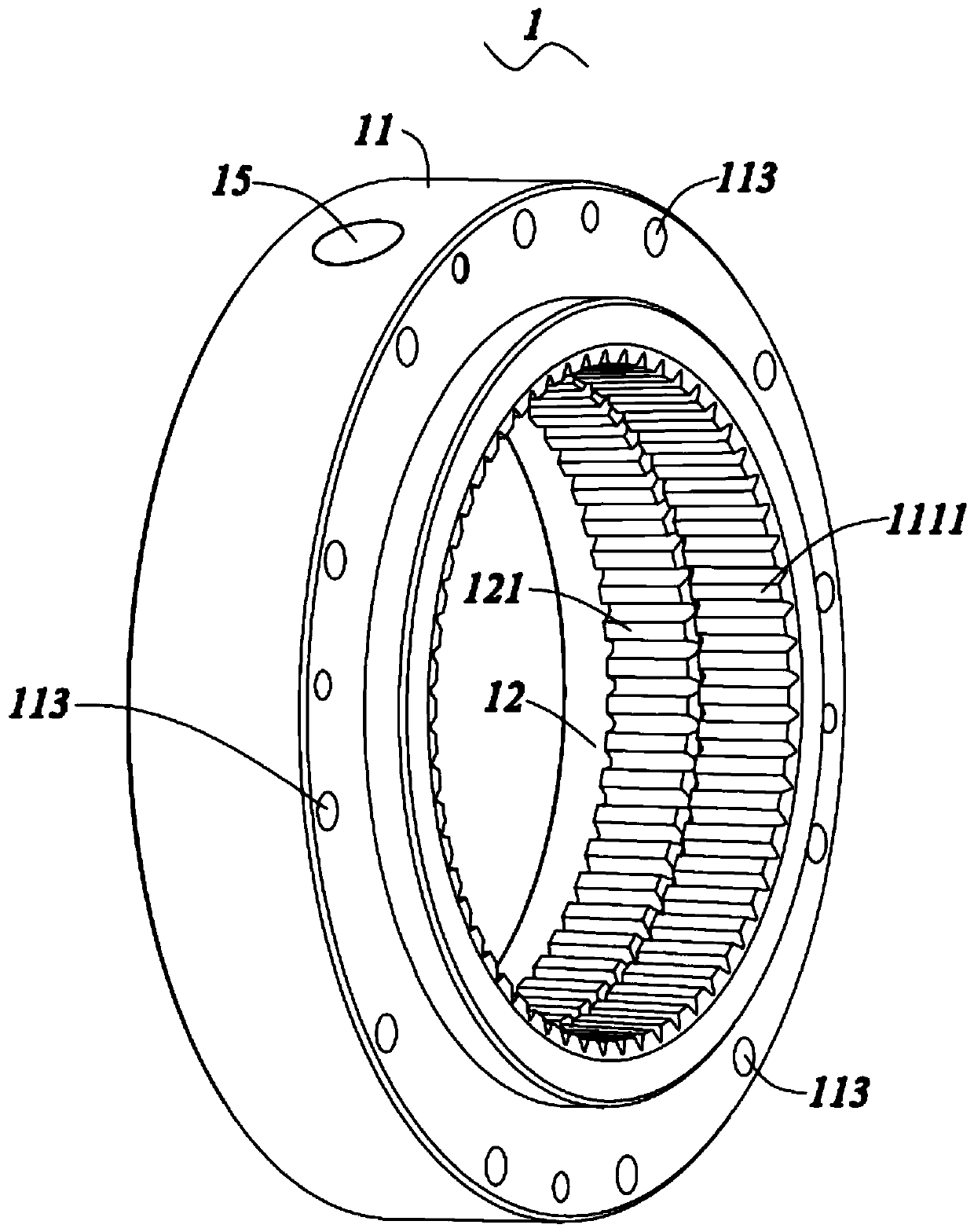
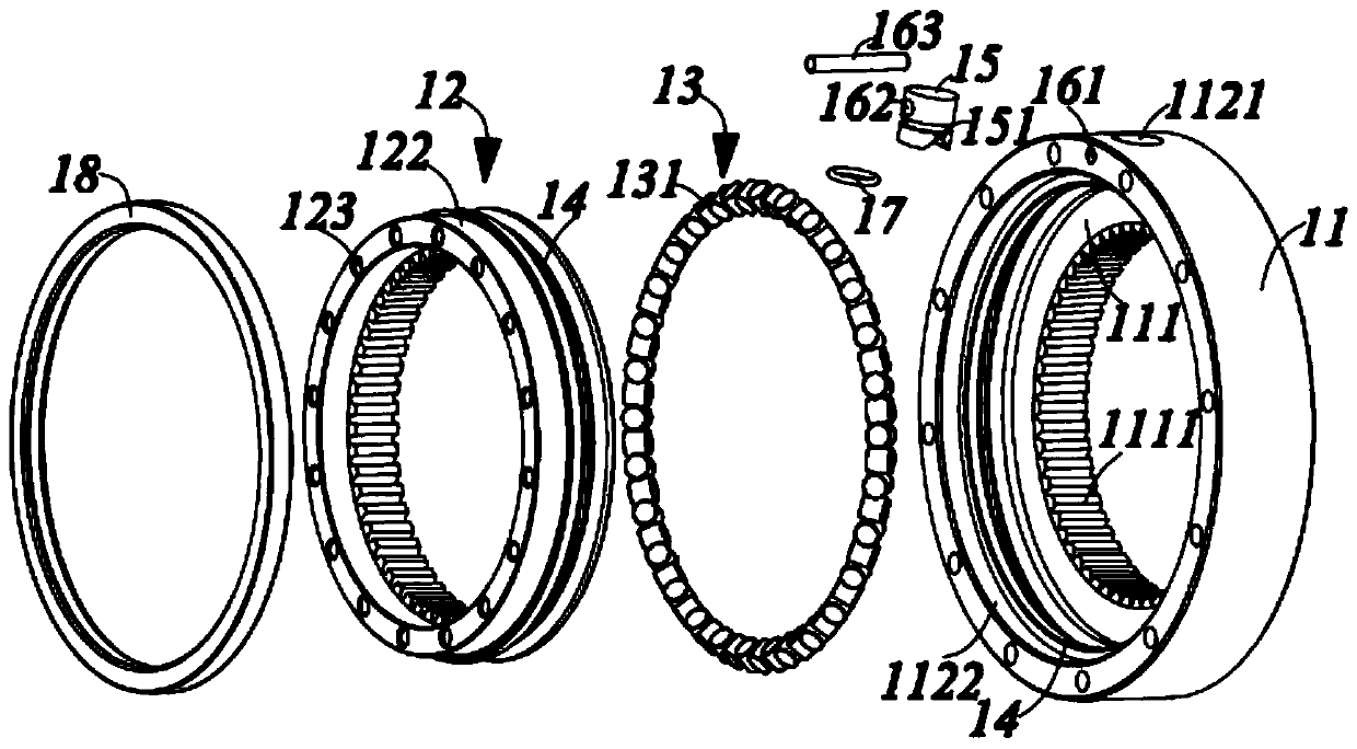
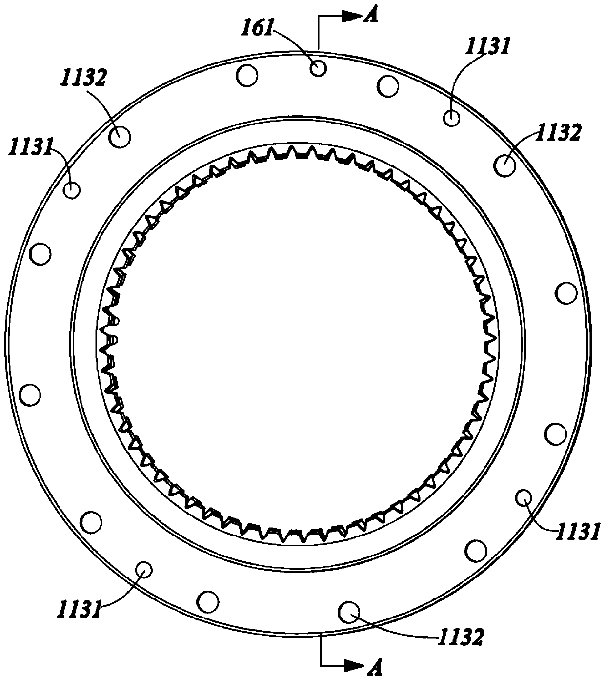
[0026] The present invention will be described in detail below in conjunction with various embodiments shown in the accompanying drawings, please refer to Figure 1 to Figure 9 Shown is a preferred embodiment of the present invention. However, it should be noted that these embodiments do not limit the present invention, and any functional, method, or structural equivalent transformations or substitutions made by those skilled in the art based on these embodiments fall within the protection scope of the present invention.

[0027] Please refer to Figure 1 to Figure 5 As shown, the present invention provides a cross roller bearing 1 , including an outer ring bearing 11 , an inner ring bearing 12 , and a rolling assembly 13 arranged between the outer ring bearing 11 and the inner ring bearing 12 .

[0028] The outer ring bearing 11 has a first outer ring 111 and a second outer ring 112 arranged coaxially along its axial direction, and the inner diameter of the first outer ring ...


PUM


Abstract

The invention provides a crossed roller bearing and a speed reducer. The crossed roller bearing comprises an outer ring bearing, an inner ring bearing arranged coaxial with the outer ring bearing, anda rolling assembly arranged between the outer ring bearing and the inner ring bearing, wherein the outer ring bearing is provided with a first outer circular ring and a second outer circular ring which are coaxially arranged along the axial direction of the outer ring bearing, the inner diameter of the first outer circular ring is smaller than the inner diameter of the second outer circular ring,the inner ring bearing is located on the inner side of the second outer circular ring, and the rolling assembly is located between the inner ring bearing and the second outer circular ring; and the inner circumference of the first outer circular ring is provided with a first inner gear ring, and the inner circumference of the inner ring bearing is provided with a second inner gear ring. The crossed roller bearing can be directly applied to the NGWN type speed reducer or the NN type speed reducer, and can substantially reduce the axial installation space required by the NGWN type speed reduceror the NN type speed reducer at the same time, so that the speed reducer is compact in structure, simple and good in reliability, and can achieve high-precision and high-rigidity transmission.

Description

technical field [0001] The invention relates to the field of bearings, in particular to a cross-roller bearing suitable for NGWN-type reducers and NN-type reducers and a reducer with the cross-roller bearing. Background technique [0002] The crossed roller bearing is a special type of bearing in which the inner and outer rings are separated from each other. At the same time, cross-set rollers are placed in the V-shaped groove between the inner ring and the outer ring to prevent the inner ring from contacting the outer ring. The rings are separated from each other. On the one hand, due to the split structure between the inner ring and the outer ring, the bearing clearance can be adjusted, and even if a preload is applied, high-precision rotational motion can be obtained; on the other hand, because the inner ring is adjacent The rollers are arranged crosswise, so that the cross-roller bearing can bear axial and radial loads and overturning moments at the same time. Therefore,...

Claims


Application Information

Patent Timeline
Patent Type & Authority Applications(China)
IPC IPC(8): F16C19/36F16C33/58F16C33/78F16H57/02
CPCF16C19/362F16C33/581F16C33/7803F16C33/7823F16C33/7886F16C2361/61F16H57/02F16H2057/02086
Inventor 张连新
Owner QUANTA MACHINERY CO LTD
Learn More