
Power supply cable unlocking device applied to server

A technology of power supply cable and unlocking device, applied in the server field, can solve the problems of time-consuming and laborious, large use force, damage to the wire end connector or board end connector, etc., so as to reduce the use cost, improve the work efficiency, and improve the contact area effect

Active Publication Date: 2020-02-25
INSPUR SUZHOU INTELLIGENT TECH CO LTD
View PDF17 Cites 0 Cited by
  • Summary
  • Abstract
  • Description
  • Claims
  • Application Information

AI Technical Summary

Problems solved by technology

[0002] In the internal components of the server, the power cable is an indispensable part. The power cable is connected to the corresponding board end connector to supply power. At present, the commonly used line end power supply cables are PH3.0 and PH4.2 specifications. Wire-end connectors, but because the structure of this type of wire-end connectors is relatively tight when connected to the board-end connectors, it takes a lot of force to pull out the wire-end connectors. When the staff uses too much force, the pulled out wires The end connector or board end connector will be damaged, especially when the number of PINs is large and the internal space structure is small, the staff's hands cannot act on the buckle of the line end connector to unlock, resulting in the staff being unable to Unlock the wire-end connector normally and pull out the cable (especially for PH3.0 cables). At the same time, the edges and corners of the wire-end connector are particularly sharp, which is easy to scratch your hands during the pull-out process. The process of pulling out the end connector is time-consuming and laborious, and is also restricted by the internal space environment of the server, which reduces the work efficiency when the end connector is pulled out, and at the same time there is a risk of scratching hands

Method used


Image

  • Power supply cable unlocking device applied to server
  • Power supply cable unlocking device applied to server
  • Power supply cable unlocking device applied to server

Examples


Embodiment Construction

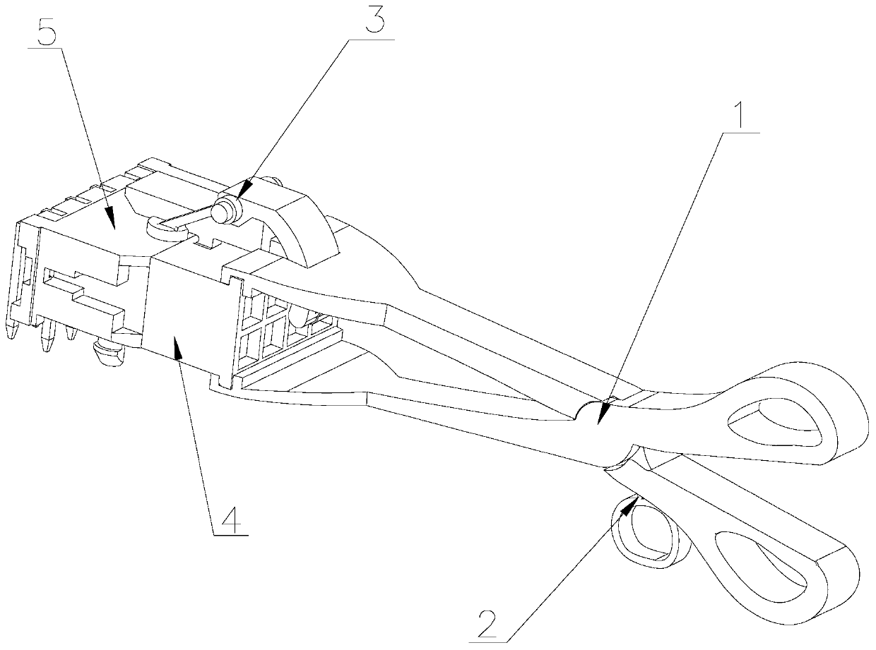
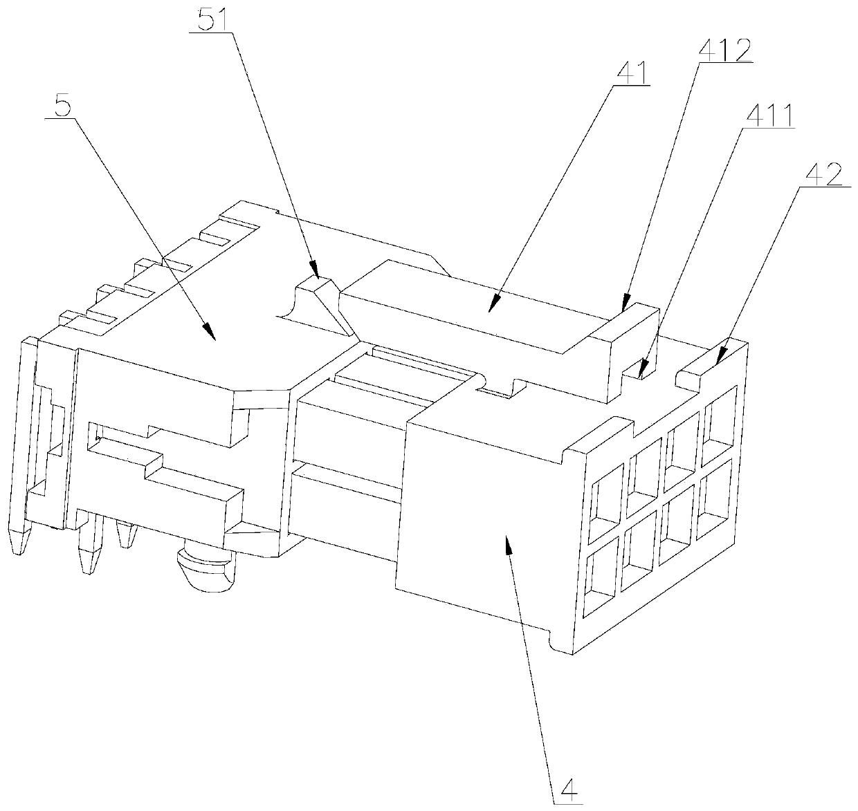
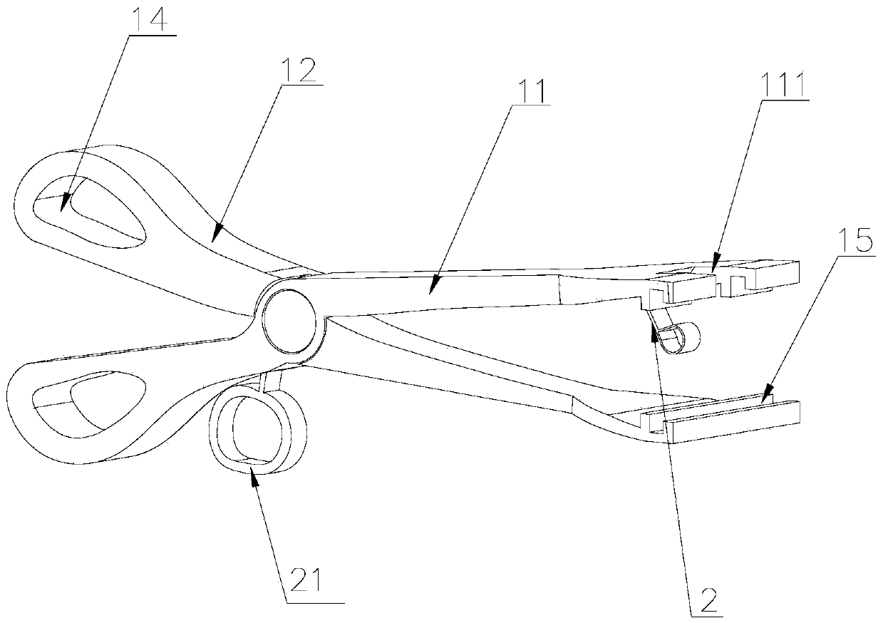
[0032] Attached below Figure 1-6 , clearly and completely describe the technical solutions in the embodiments of the present invention, obviously, the described embodiments are only some of the embodiments of the present invention, not all of them. Based on the embodiments of the present invention, all other embodiments obtained by persons of ordinary skill in the art without making creative efforts belong to the protection scope of the present invention.

[0033] In describing the present invention, it should be understood that the terms "longitudinal", "transverse", "upper", "lower", "front", "rear", "left", "right", "vertical", The orientations or positional relationships indicated by "horizontal", "top", "bottom", "inner", "outer", etc. are based on the orientations or positional relationships shown in the drawings, and are only for the convenience of describing the present invention, rather than indicating or It should not be construed as limiting the invention by imply...


PUM


Abstract

The invention discloses a power supply cable unlocking device applied to a server. The device comprises a clamping mechanism, a pull belt and an unlocking mechanism; the clamping mechanism comprises afirst clamping handle and a second clamping handle; the first clamping handle is rotationally installed on the second clamping handle; a cavity is formed in the first clamping handle; the pull belt is arranged in the cavity; and the two ends of the pull belt extend out of the first clamping handle. According to the invention, a wire end connector is fixed through the clamping mechanism, the pullbelt is pulled to drive the unlocking mechanism to rotate and the unlocking mechanism rotates to press and unlock a buckle on the wire end connector, so that the wire end connector and the power supply cable can be integrally pulled out of a board end connector quickly, time and labor are saved, the working efficiency is improved, a worker does not need to touch the wire end connector with hands in the whole unlocking process, and the safety during working is improved.

Description

technical field [0001] The invention belongs to the technical field of servers, and in particular relates to an unlocking device applied to power supply cables of servers. Background technique [0002] In the internal components of the server, the power cable is an indispensable part. The power cable is connected to the corresponding board end connector to supply power. At present, the commonly used line end power supply cables are PH3.0 and PH4.2 specifications. Wire-end connectors, but because the structure of this type of wire-end connectors is relatively tight when connected to the board-end connectors, it takes a lot of force to pull out the wire-end connectors. When the staff uses too much force, the pulled out wires The end connector or board end connector will be damaged, especially when the number of PINs is large and the internal space structure is small, the staff's hands cannot act on the buckle of the line end connector to unlock, resulting in the staff being un...

Claims


Application Information

Patent Timeline
Patent Type & Authority Applications(China)
IPC IPC(8): H01R13/502H01R13/627H01R13/629H01R13/639
CPCH01R13/502H01R13/627H01R13/629H01R13/639
Inventor 祝全志
Owner INSPUR SUZHOU INTELLIGENT TECH CO LTD
Learn More